Component installation method and component installation device

A technology for parts installation and parts, which is applied in the field of parts installation devices, and can solve the problems of large-scale installation heads of suction nozzles, etc.

Inactive Publication Date: 2013-10-30
PANASONIC CORP
View PDF1 Cites 4 Cited by
  • Summary
  • Abstract
  • Description
  • Claims
  • Application Information

AI Technical Summary

Problems solved by technology

Therefore, the suction nozzle needs to have a higher pressing force than conventional ones, and if simply increasing the pressing force of the suction nozzle, there is a problem of increasing the size of the mounting head equipped with the suction nozzle.

Method used


Image

  • Component installation method and component installation device
  • Component installation method and component installation device
  • Component installation method and component installation device

Examples


Embodiment Construction

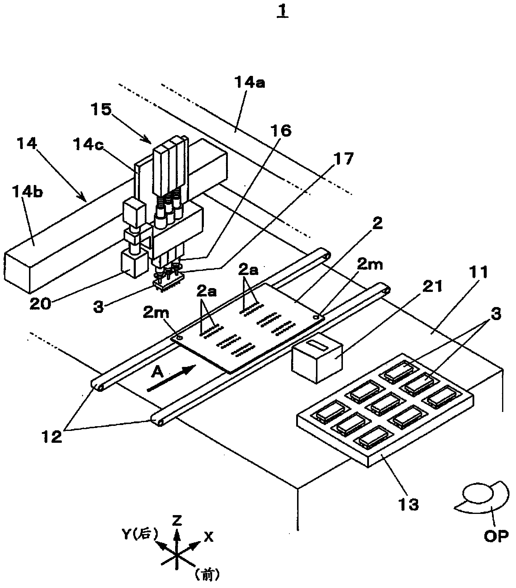
[0035] Hereinafter, embodiments of the present invention will be described with reference to the drawings. figure 1 The shown component mounting device 1 repeatedly carries out the loading and positioning operations of the substrate 2 conveyed by the device (such as a solder printing machine or other component mounting device) on the upstream process side not shown in the figure, and the components (electronic components) 3 The surface of a series of component mounting processes consisting of the mounting operation on the positioned substrate 2 and the unloading operation to the downstream process side equipment (such as other component mounting equipment, inspection machines, reflow furnaces, etc.) on the substrate 2 on which the component 3 is mounted. Mounting type parts mounting device. Hereinafter, for convenience of description, the conveying direction of the substrate 2 is defined as the X-axis direction (the left-right direction viewed from the operator OP), and the ho...


PUM


Abstract

The object of the invention is to provide a component installation method and a component installation device, capable of preventing increasing the size of an installation head with a nozzle and pressing components requiring higher pressure into a substrate. After a component (3) is attached to one of absorption nozzles (17), namely a first absorption nozzle (17a), of an installation head (15), and a plurality of insertion pins (3a) of the component (3) are situated above a plurality of insertion holes (2a) of a substrate (2), the component (3) is pressed into the substrate (2) in such a manner that the first absorption nozzle (17a) cooperates with a second absorption nozzle (17b) different from the first absorption nozzle (17a) among the absorption nozzles (17) to lower the first absorption nozzle (17a) and the second absorption nozzle (17b) and to press the insertion pins (3a) of the component (3) into the insertion holes (2a) of the substrate (2).

Description

technical field [0001] The present invention relates to a component mounting method and a component mounting device for mounting a component on a substrate by press-fitting a component having a plurality of insertion pins extending downward into a plurality of pin insertion holes provided in a substrate. Background technique [0002] Conventionally, as a component mounting device that press-fits a component having a plurality of insertion pins extending downward into a plurality of pin insertion holes provided in a substrate to mount the component to the substrate, a chuck is known for holding the component. A device of the type that presses the part toward the substrate after inserting pins and pin insertion holes to align them (for example, Patent Document 1). In this type of component mounting device, the substrate can be inserted while the component is firmly held by the chuck, so the component can be securely mounted on the substrate by pressing the component only once ...

Claims


Application Information

Patent Timeline
Patent Type & Authority Applications(China)
IPC IPC(8): H05K13/04
Inventor 川瀬健之
Owner PANASONIC CORP
Why Eureka
Try Eureka