Power conversion device, motor drive device provided therewith, fan provided with said motor drive device, compressor, and air conditioner, refrigerator, and freezer provided with said fan and compressor

A technology for a power conversion device and a motor, which is applied in the fields of power conversion devices and motor drive devices, can solve problems such as complicated control software, and achieve the effect of improving performance

Active Publication Date: 2015-11-18
MITSUBISHI ELECTRIC CORP
View PDF7 Cites 16 Cited by
  • Summary
  • Abstract
  • Description
  • Claims
  • Application Information

AI Technical Summary

Problems solved by technology

In the structure where the shunt resistance of the power supply or the shunt resistance of the lower arm is provided, the control software is complicated because the detected phase current needs to be determined for each phase

Method used


Image

  • Power conversion device, motor drive device provided therewith, fan provided with said motor drive device, compressor, and air conditioner, refrigerator, and freezer provided with said fan and compressor
  • Power conversion device, motor drive device provided therewith, fan provided with said motor drive device, compressor, and air conditioner, refrigerator, and freezer provided with said fan and compressor
  • Power conversion device, motor drive device provided therewith, fan provided with said motor drive device, compressor, and air conditioner, refrigerator, and freezer provided with said fan and compressor

Examples


Embodiment approach

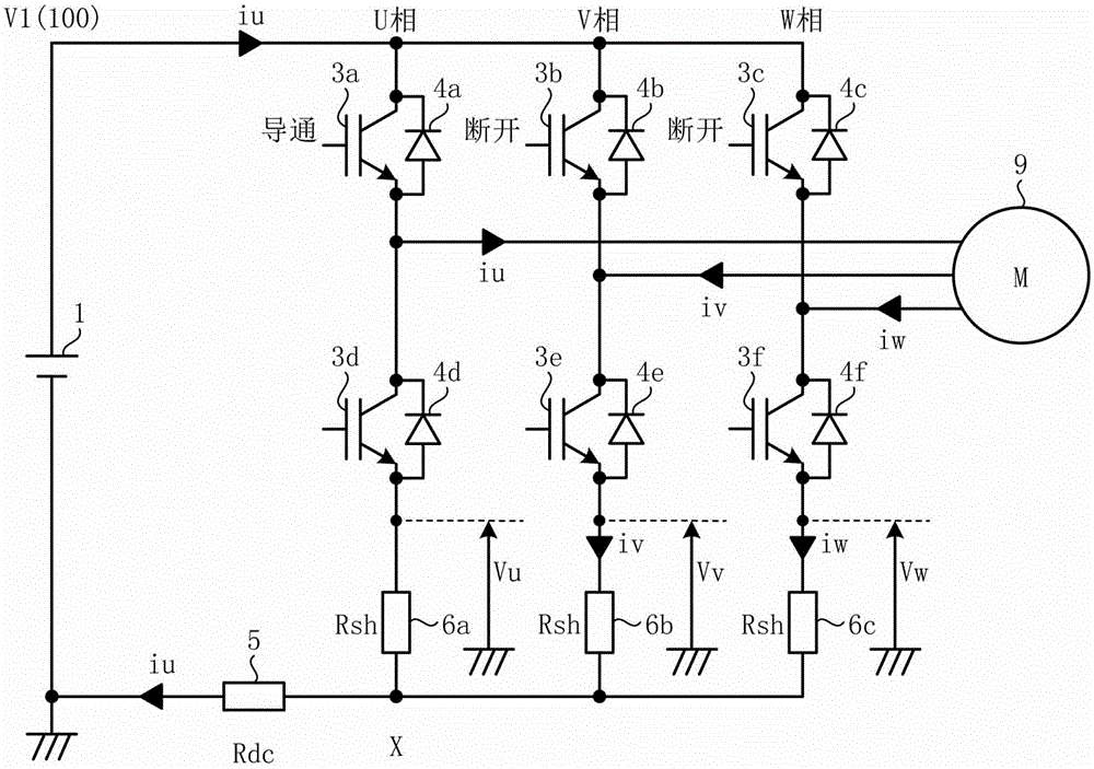
[0054] figure 1 It is a figure which shows one structural example of the power conversion apparatus concerning embodiment. exist figure 1 In the example shown, the power conversion device 100 according to the embodiment is configured to convert the DC power supplied from the DC power supply 1 into figure 1 In the example shown is a 3-phase alternating current supplied by an electric motor 9 .

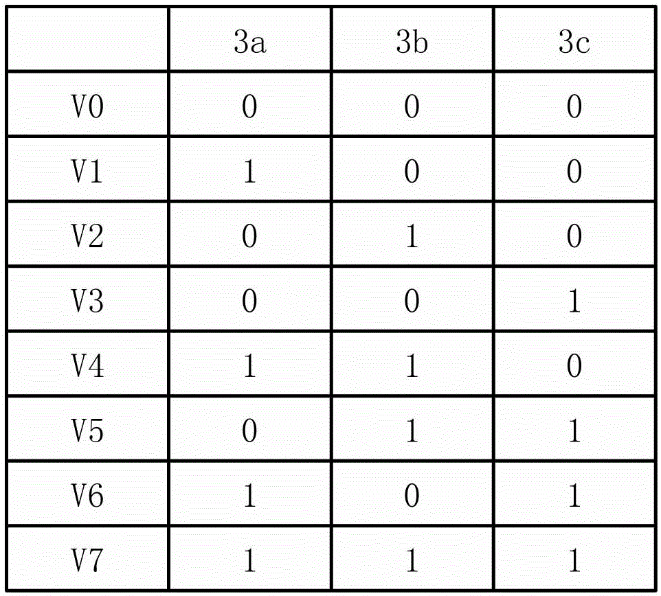
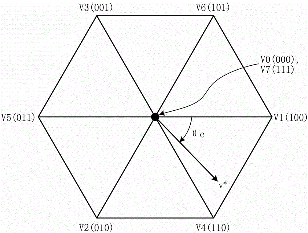
[0055] Such as figure 1 As shown, the power conversion device 100 has the following main components for supplying 3-phase AC power to the load device 9: an inverter 2, which is composed of 3 bridge arms, and the 3 bridge arms include: an upper bridge arm switching element 3a to 3c (here, 3a: U phase, 3b: V phase, 3c: W phase) and lower arm switching elements 3d to 3f (here, 3d: U phase, 3e: V phase, 3f: W phase); and control part 7, which generates six drive signals corresponding to the upper arm switching elements 3a to 3c of each phase and the lower arm switching elements 3d to 3f...


PUM


Abstract

To obtain a power conversion device that makes it possible to: both lengthen phase-current detection periods and simplify detection procedures; and control a carrier frequency so as to improve device performance. A power-supply shunt resistance (5) is provided between the load-voltage side of a DC power supply (1) and an inverter (2), and a lower-arm shunt resistance (6a through 6c) for each phase is provided between a lower-arm switching element (3d through 3f) for that phase and the power-supply shunt resistance (5). For each phase, a lower-arm voltage is detected, said lower-arm voltage being the voltage between the load-voltage side of the DC power supply (1) and the point where the lower-arm switching element (3d through 3f) for that phase connects to the lower-arm shunt resistance (6a through 6c) for that phase. The amount of current flowing through a load device (9) in each phase is computed on the basis of the detected lower-arm voltages, and the carrier frequency of a carrier signal, which serves as a base frequency for drive signals, is controlled in accordance with changes in a specific control parameter (A).

Description

technical field [0001] The present invention relates to a power conversion device, a motor drive device including the same, a blower and a compressor including the same, and an air conditioner, a refrigerator, and a refrigerator including these. Background technique [0002] In a power conversion device, for example, the phase current flowing in a 3-phase load such as a motor is detected, and the load is controlled based on the current of each phase. The ON / OFF state of the switching element of the inverter is combined to generate a 3-phase AC voltage and supply it to the load. [0003] As a method of detecting each phase current flowing into a three-phase load, there is a method of providing a current sensor or a shunt resistor connected in series to a switching element constituting an inverter. As a structure for installing a shunt resistor, there are: a structure for installing a power supply shunt resistor for detecting the current between the DC power supply and the in...

Claims


Application Information

Patent Timeline
Patent Type & Authority Applications(China)
IPC IPC(8): H02M7/5387
CPCH02M7/53875H02M2001/0009H02P2205/01H02P27/085H02M1/0009H02M7/501H02M7/5395
Inventor 下麦卓也植村启介有泽浩一筱本洋介梅原成雄浦慎一郎谷川诚
Owner MITSUBISHI ELECTRIC CORP
Why Eureka
Try Eureka