Check patentability & draft patents in minutes with Patsnap Eureka AI!

an optical cable assembly

A technology of optical cable components and optical fibers, applied in the field of optical cable components, can solve the problems that signals cannot be transmitted from one optical fiber ribbon to another optical fiber ribbon, crossing in up and down directions cannot be realized, signal crossing is inevitable, etc.

Active Publication Date: 2016-12-07
CHINA AVIATION OPTICAL-ELECTRICAL TECH CO LTD
View PDF4 Cites 0 Cited by
  • Summary
  • Abstract
  • Description
  • Claims
  • Application Information

AI Technical Summary

Problems solved by technology

When this form of optical fiber transmits signals, there is a one-to-one correspondence between the signals at one end and the other end, and the signal cannot be transmitted from one optical fiber ribbon to another optical fiber ribbon. As the processing capacity of information system data increases, Signal crossing between fiber optic ribbons is inevitable. Existing fiber optic backplanes with intersecting fiber optic ribbons are used, such as the fiber optic backplane disclosed in US Patent No. 6,744,956. The fiber optic backplane includes first fiber optic backplane units stacked up and down. and a second optical fiber backplane unit, the second optical fiber backplane unit includes a first backplane base, the second optical fiber backplane unit includes a second backplane base, two first optical fiber ribbons are arranged on the first backplane base, and the second Two second optical fiber ribbons are arranged on the base of the second backplane, the fiber inlet ends of the two first optical fiber ribbons are arranged at intervals left and right, the fiber inlet ends of the two second optical fiber ribbons are arranged at intervals left and right, and the two first optical fiber ribbons are arranged at intervals left and right. The fiber-entry ends of the first and second fiber ribbons are above the fiber-entry ends of the two second fiber ribbons, and the fiber outlet ends of the first and second fiber ribbons are crossed and recombined to form four new fiber ribbons to complete the cross-transmission of optical fiber signals. The fiber outlet end of the first fiber optic ribbon is above the fiber outlet end of the second fiber optic ribbon
The problem with the existing optical fiber backplane is that the optical fibers between the optical fiber backplane units can only cross in the horizontal direction, but not in the vertical direction. It is above the fiber inlet end of the second fiber ribbon, and the fiber outlet end of the first fiber ribbon is above the fiber outlet end of the second fiber ribbon. With the rapid development of communication equipment, the application of multi-row high-density fiber optic connectors is increasing. The more extensive, when the signals between rows of multi-row fiber optic connectors are interactively connected, this kind of fiber optic backplane cannot solve the problem

Method used


Image

  • an optical cable assembly
  • an optical cable assembly
  • an optical cable assembly

Examples


Embodiment Construction

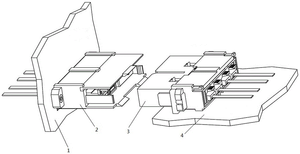
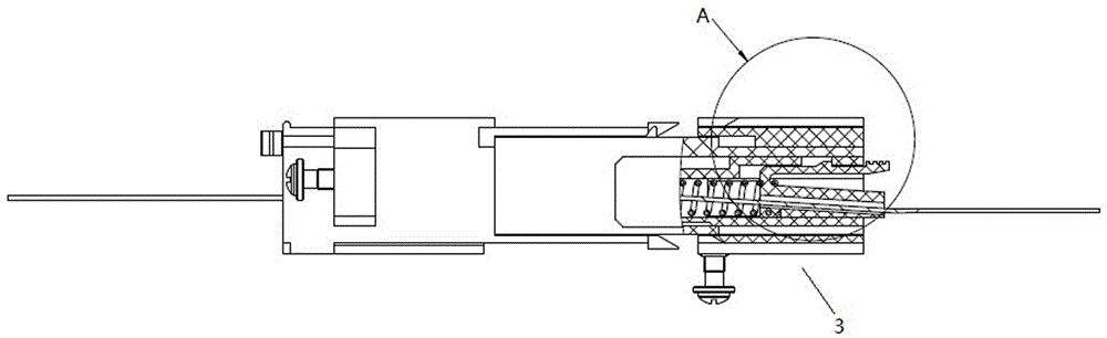
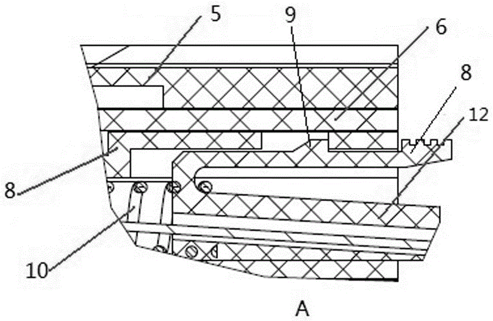
[0026] Examples of fiber optic cable assemblies are Figure 1~15 As shown: the optical cable assembly includes an optical fiber connector and an optical fiber backplane. In this embodiment, the optical fiber connector is a sub-board plug installed on a sub-board in a corresponding cabinet during use. The sub-board plug 3 includes a plug housing and a plug housing The body includes a plug part housing 8, a locking housing 6 and a floating housing 5, wherein the front end of the plug part housing is a plug end, the plug part housing is made of insulating material, and the plug part housing is provided with contacts unit, the contact unit includes a pin body 11 and a limit seat 12 arranged front and rear. In this embodiment, the limit seat is a two-body limit seat, and the pin body includes MT pins. 8. The elastic arm 8 is provided with a locking protrusion 9, and the plug part housing 8 is provided with a card slot that cooperates with the locking protrusion 9, and a first sprin...


PUM


Abstract

The invention relates to an optical cable assembly, and the assembly comprises an optical fiber connector and an optical fiber back plate. A first optical fiber back plate unit of the optical fiber back plate comprises a first back plate base body, and the first back plate base body of the first optical fiber back plate unit is provided with a first back plate through groove. A second back plate base body of a second back plate unit of the optical fiber back plate comprises a second back plate right segment which is located above the first back plate base body and is used for the arrangement of an outgoing wire end of the second optical fiber, a second back plate left segment which is located below the first back plate base body and is used for the arrangement of an incoming wire end of the second optical fiber, and a second back plate central segment which is connected between the second back plate left segment and the second back plate right segment. The second back plate central segment passes through the first back plate through groove, and an incoming wire end of a second optical fiber is located below an incoming wire end of a first optical fiber belt. An outgoing wire end of the second optical fiber is located above an outgoing wire end of the first optical fiber belt. The assembly provided by the invention can achieve that the optical fiber among the optical fiber back plate units can be intersected with each other vertically.

Description

technical field [0001] The invention relates to optical cable assemblies in the field of optical signal transmission. Background technique [0002] With the continuous development of information technology, optical fiber transmission is used in more and more communication systems. In order to achieve high-density transmission of optical signals, the application of optical fiber ribbons containing multiple optical fibers is born. The traditional optical fiber ribbons are flat ribbons. Form, which consists of 4, 8, 12, 24 or other numbers of bare optical fibers side by side. When used, a special type of connector is made at the input end of the optical fiber and the output end of the optical fiber to transmit optical signals. When this form of optical fiber transmits signals, there is a one-to-one correspondence between the signals at one end and the other end, and the signal cannot be transmitted from one optical fiber ribbon to another optical fiber ribbon. As the processing...

Claims


Application Information

Patent Timeline
Patent Type & Authority Patents(China)
IPC IPC(8): G02B6/36
CPCG02B6/3608G02B6/3628
Inventor 刘卫锋黄澄刘涛孙亚磊周生贺
Owner CHINA AVIATION OPTICAL-ELECTRICAL TECH CO LTD
Features
  • R&D
  • Intellectual Property
  • Life Sciences
  • Materials
  • Tech Scout
  • Unparalleled Data Quality
  • Higher Quality Content
  • 60% Fewer Hallucinations
Learn More