
Surface difference detection tool and surface difference detection method of stamping parts

A detection method and technology of stamping parts, which are applied in the direction of measuring devices, mechanical measuring devices, instruments, etc., can solve the problems of inaccurate part precision test results, inability to guarantee the accuracy of part precision test results, and deviation of test results, etc.

Active Publication Date: 2017-11-10
ANHUI JIANGHUAI AUTOMOBILE GRP CORP LTD
View PDF3 Cites 0 Cited by
  • Summary
  • Abstract
  • Description
  • Claims
  • Application Information

AI Technical Summary

Problems solved by technology

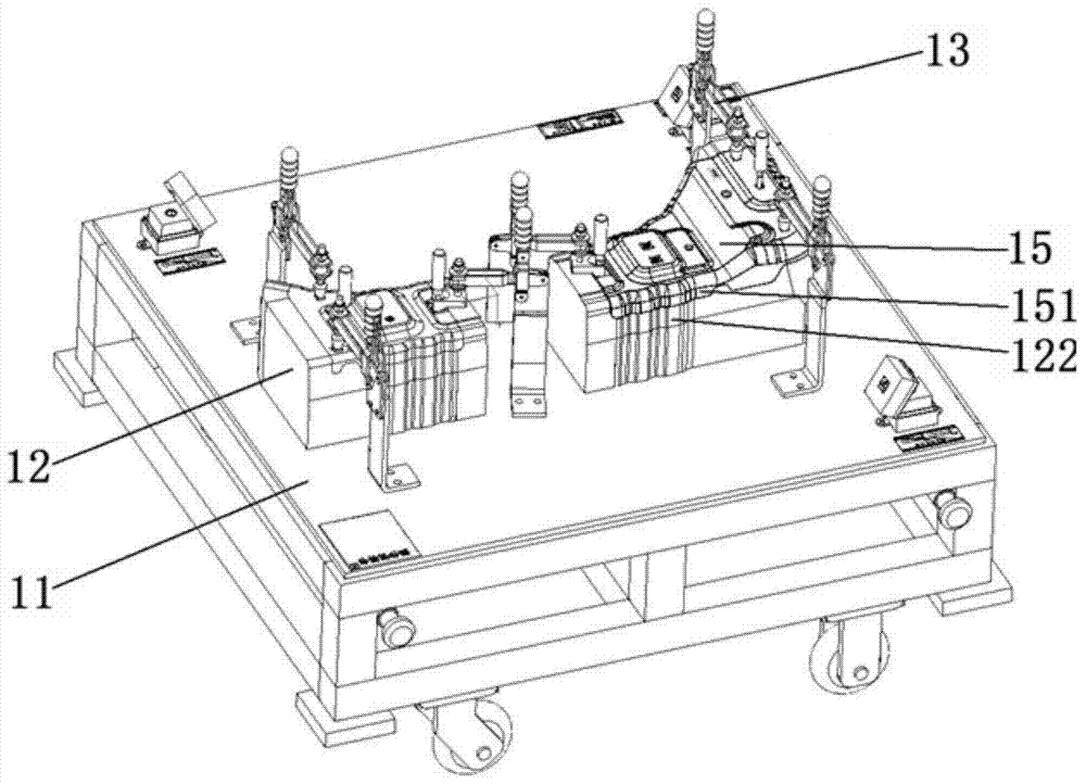
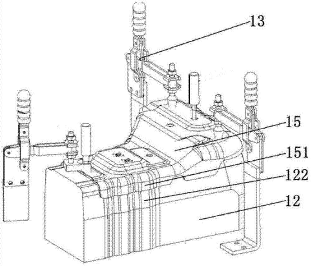
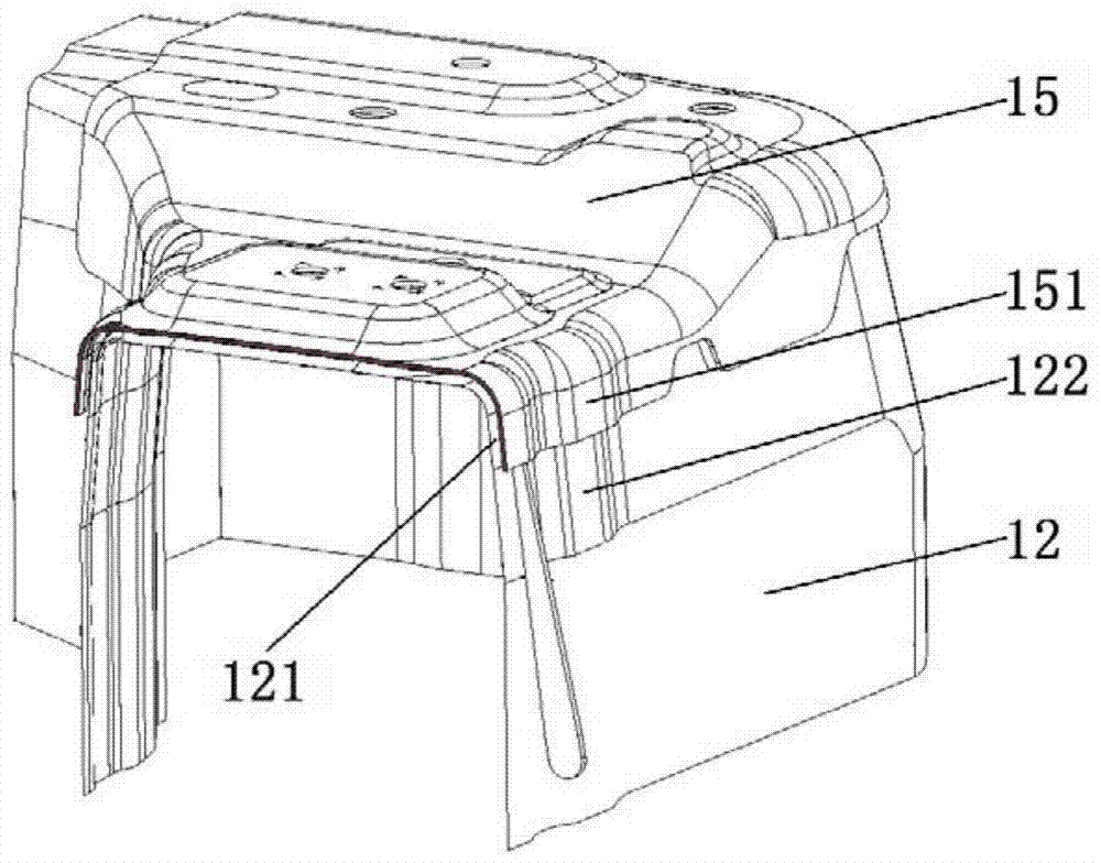
[0005] However, the surface difference detection tool for stamping parts corresponds to the surface difference detection of stamping parts by inserting the gap ruler vertically into the edge of the part and the difference between the length of the processing surface of the inspection tool body and the reference value to judge whether the part is qualified, mainly through manual operation Insert the tip of the gap ruler and read it visually. This detection method has a large human influence factor (the force of the gap ruler insertion, the estimated reading), and the accuracy of the part precision test results cannot be guaranteed; at the same time, the existing The length specification of the gap ruler is 150mm. When the height of the inspection tool body is low and the distance between the edge of the part and the base of the inspection tool is small, the gap ruler cannot be perpendicular to the flange part and vertical Inserting it into the edge of the product for correct detection, the gap gauge can only be tilted for detection, which leads to deviations in the detection results, and the part precision detection results are inaccurate, which cannot provide an effective basis for the rectification of stamping parts and the improvement of the accuracy of the whole vehicle. The method to avoid this problem will increase the cost of the inspection tool; in addition, for some stamping parts, when the flanging part is short or the shape is irregular, the gap ruler will be adjacent to the corresponding position on the inspection tool body when inserted. Surface interference, unable to perform normal detection

Method used


Image

  • Surface difference detection tool and surface difference detection method of stamping parts
  • Surface difference detection tool and surface difference detection method of stamping parts
  • Surface difference detection tool and surface difference detection method of stamping parts

Examples


Embodiment Construction

[0032] The core of the present invention is to provide a surface difference inspection tool for stamping parts, in order to improve the detection accuracy, avoid interference with adjacent profiles of the parts to be tested, and improve the performance of the inspection tool. Another core of the present invention is to provide a detection method based on the above-mentioned surface difference detection tool for stamping parts.

[0033] In order to enable those skilled in the art to better understand the technical solutions of the present invention, the present invention will be further described in detail below in conjunction with the accompanying drawings.

[0034] Please refer to Figure 4 and Figure 5 , Figure 4 It is a structural schematic diagram of a specific embodiment of the surface difference inspection tool for stamping parts provided by the present invention; Figure 5 for Figure 4 The local enlarged view of the surface difference inspection tool for the stam...


PUM


Abstract

The invention discloses a stamping part surface difference test tool, comprising a base and a test tool body installed in the base. The test tool body is provided with a flanging portion processing molded surface. The shape of the flanging portion processing molded surface is the same with the shape of the flanging portion of a to-be-tested part, and the flanging portion processing molded surface is provided with a preset gap. A detection extension portion is arranged under the flanging portion processing molded surface. The outer surface of the detection extension portion is formed on an extension plane of the outer surface of the flanging portion. Thus, a problem that surface difference precision of a component flanging portion cannot be detected effectively when the test tool body is relatively low is solved, and influence on precision caused by human factors in detection is prevented, and authenticity and accuracy of product precision detection are effectively improved. The invention also provides a detection method based on the stamping part surface difference test tool.

Description

technical field [0001] The invention relates to the technical field of inspection tools, in particular to a surface difference inspection tool for stamping parts. The present invention also relates to a surface difference detection method based on the above stamping part surface difference inspection tool. Background technique [0002] In the welding and manufacturing process of automobile bodies, the accuracy of the body-in-white is the main indicator of the welding process level. High-precision body-in-white can not only improve the assembly of assembly parts, but also improve the quality of the body's appearance gap. At present, in the whole vehicle development process, most of the stamping parts and welding assemblies of automobiles are inspected and accepted by inspection tools to confirm whether the precision of the stamping parts hole and the contour of the surface are qualified to meet the loading requirements. [0003] Please refer to Figure 1-Figure 3 , figure ...

Claims


Application Information

Patent Timeline
Patent Type & Authority Patents(China)
IPC IPC(8): G01B5/00
Inventor 陈世涛王海玲何鹏申郭奔李辉阮林凡
Owner ANHUI JIANGHUAI AUTOMOBILE GRP CORP LTD
Learn More