A fall-back stop mechanism for a super-large falling device

A stop mechanism, super-large technology, applied in the direction of measuring devices, machine/structural component testing, impact testing, etc., can solve accidental injuries, time-consuming and labor-intensive problems, and achieve the effect of simple structure

Active Publication Date: 2017-09-29
GENERAL ENG RES INST CHINA ACAD OF ENG PHYSICS
View PDF5 Cites 0 Cited by
  • Summary
  • Abstract
  • Description
  • Claims
  • Application Information

AI Technical Summary

Problems solved by technology

During the drop test, using manual unlocking is not only time-consuming and labor-intensive, but also accidental injuries may occur if the product test vehicle is not reliably connected to the slow-down system

Method used


Image

  • A fall-back stop mechanism for a super-large falling device
  • A fall-back stop mechanism for a super-large falling device
  • A fall-back stop mechanism for a super-large falling device

Examples


Embodiment Construction

[0033] The present invention will be further described below in conjunction with accompanying drawing:

[0034] In order to facilitate the description of the specific structure of the fall-back stop mechanism of the present invention, the preferred structure of the super-large drop device of the present invention is first described here, specifically as follows:

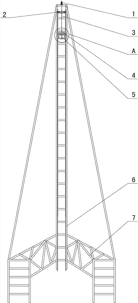
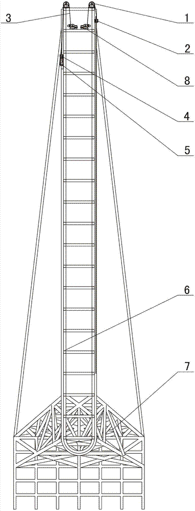
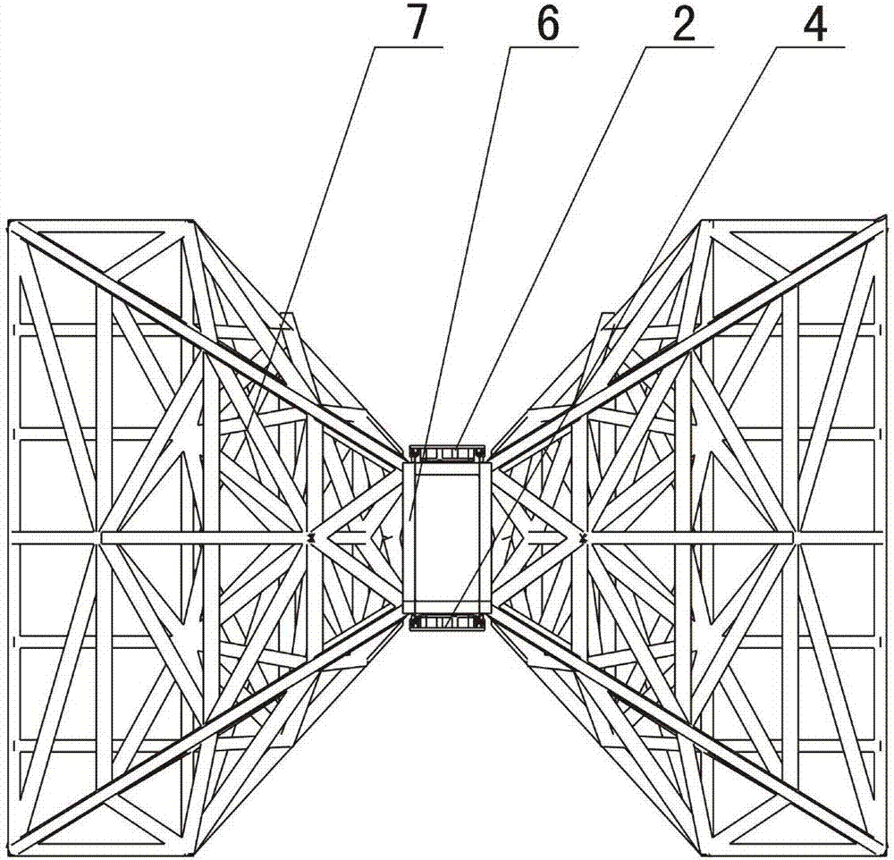
[0035] Such as Figure 1-Figure 4 As shown, the preferred super-large drop device includes a drop tower 7, a track 6, and a product test vehicle 5 for placing and driving a test product, a traction lifting trolley 4, a traction slow-down trolley 2, an electromagnet gripper 9a, an electromagnetic The iron suction plate 9b and the fall-back stop device, the track 6 is installed on the drop tower 7, the product test vehicle 5 is installed on the track 6, and the bottom of the track 6 is "U" shaped, and the product test vehicle 5 is initially installed on the track 6 The vertical section is the first section of the trac...


PUM


Abstract

The invention discloses a fall-back stop mechanism for a super-large drop device. The super-large drop device includes a track with a "U" shape at the bottom and a product test vehicle installed on the track; the fall-back stop mechanism includes a A plurality of protruding teeth arranged at intervals in the upper and lower directions on the end section of the track and a test vehicle stop device installed on the product test vehicle, a lower stop is provided at the position below the lowermost protruding tooth on the end section of the track, and the end section of the track The position above the convex tooth at the uppermost end is provided with an upper stopper; the test car stopper includes a mounting seat, a falling back stopper, a rotating shaft, an unlocking hook plate, a locking slide plate, a reset dial, a tension spring and a rotating shaft torsion spring . The invention adopts a set of combination mechanism to realize the automatic process of one-way movement, fall-back stop, unlocking and unlocking and reset of the product test vehicle, and has the advantages of simple structure, convenience, safety and reliability.

Description

technical field [0001] The invention relates to an auxiliary mechanism for a drop device, in particular to a fall-back stop mechanism for a super-large drop device. Background technique [0002] The drop test device is an important scientific test device that uses the earth's gravity field to simulate mechanical impacts such as drops and impacts on products during transportation and use. It is an important indicator of reliability design to test the product's anti-drop ability through this device, and it provides an important research method for reasonable product packaging design. [0003] The drop test device generally consists of a lifting mechanism, a releasing mechanism, an attitude maintaining mechanism, a buffer mechanism, and control and testing equipment. During the operation of the drop test device, a large kinetic energy will be generated. Wherein, the buffer mechanism is used for buffering and absorbing the remaining kinetic energy of the attitude maintaining m...

Claims


Application Information

Patent Timeline
Patent Type & Authority Patents(China)
IPC IPC(8): G01M7/08
Inventor 陈刚徐元利张宁平吴文凯阙兴华汪宝旭朱明智
Owner GENERAL ENG RES INST CHINA ACAD OF ENG PHYSICS
Why Eureka
Try Eureka