High-integrity container with anti-floating mechanisms for radioactive waste disposal

A radioactive waste and integrity technology, applied in portable protective containers, nuclear engineering, etc., can solve problems such as poor secondary grouting effect, unsealable workpieces, floating top of containers, etc.

Pending Publication Date: 2019-11-22
江苏希捷新能源工程技术有限公司
View PDF0 Cites 0 Cited by
  • Summary
  • Abstract
  • Description
  • Claims
  • Application Information

AI Technical Summary

Problems solved by technology

However, the workpiece will generate buoyancy under the action of concrete during the second grouting. Under the joint action of the buoyancy and the weight of the workpiece, the workpiece will float up during the second grouting. In severe cases, the top cover of the container will float up, resulting in secondary The primary grouting effect is poor or the workpiece cannot be sealed at all, which eventually leads to complete sealing failure of the workpiece

Method used


Image

  • High-integrity container with anti-floating mechanisms for radioactive waste disposal
  • High-integrity container with anti-floating mechanisms for radioactive waste disposal
  • High-integrity container with anti-floating mechanisms for radioactive waste disposal

Examples


Embodiment 1

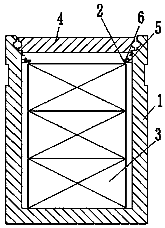
[0021] Example 1, such as figure 1 As shown, a high-integrity container for radioactive waste disposal containing an anti-floating mechanism mainly includes a container 1 with an open top, two anti-floating mechanisms 2 and three workpieces 3, the workpieces 3 are arranged in the container 1, and the anti-floating mechanism 2 Including the support 5 and the limit part 6, the anti-floating mechanism 2 is connected above the inner wall of the container 1 through the support 5, the limit part 6 can rotate along the support 5, when the workpiece 3 floats, the uppermost workpiece 3 top There is at least one contact surface or contact point with the anti-floating mechanism 2, and there is no contact surface or contact point between the top of the uppermost workpiece 3 and the support 5.

[0022] When the workpiece 3 is put into the container 1, the stop member 6 rotates downward along the support 5 or rotates left and right. Since the top of the workpiece 3 has no contact surface or...

Embodiment 2

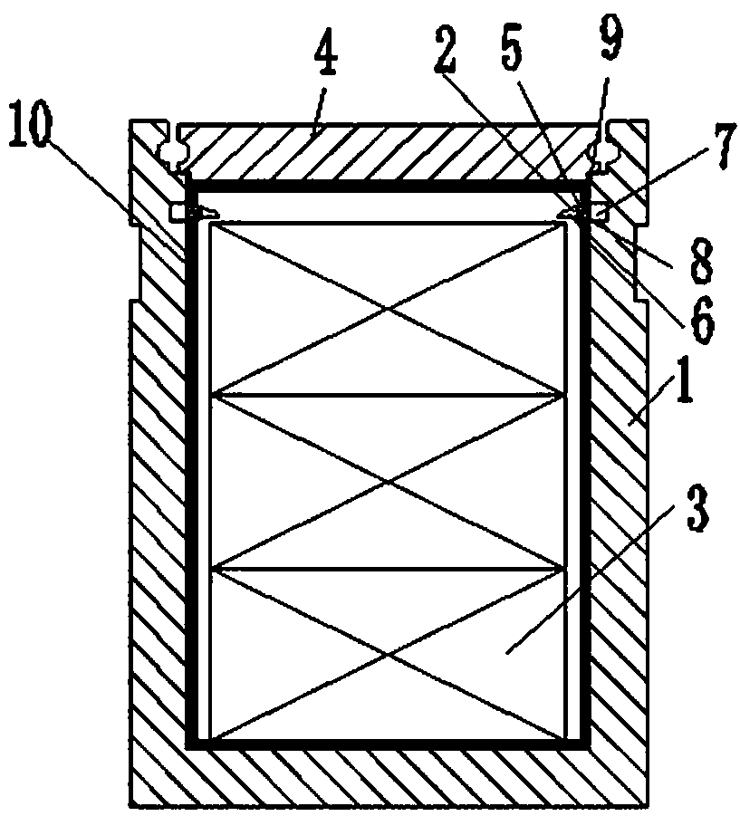
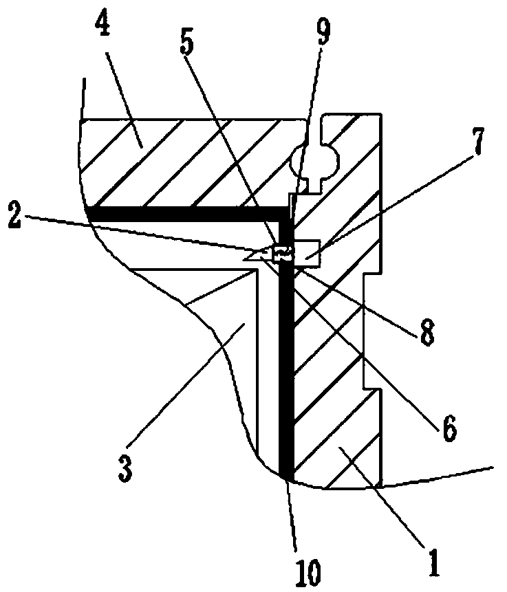
[0023] Example 2, such as figure 2 As shown, a high-integrity container for radioactive waste disposal containing an anti-floating mechanism mainly includes a container 1 with an open top, two anti-floating mechanisms 2, three workpieces 3 and a fixing device 7, and an anti-corrosion layer 10 is provided on the inner wall of the container. The workpiece 3 is arranged in the container 1, the fixing device 7 is pre-embedded in the inner wall 1 above the container 1, the material of the anti-floating mechanism 2 is a corrosion-resistant material, and the anti-floating mechanism 2 includes a support 5 and a limiting part 6, and the support 5 is connected to On the fixing device 7, through the connection of the fixing device 7, the anti-floating mechanism 2 and the container 1 are connected more firmly; the inside of the support 5 has an accommodation cavity 8 that can accommodate the limiting component 6, and the limiting component 6 passes through the elastic component 9 Connect...

Embodiment 3

[0025] Embodiment 3: Referring to Embodiment 2, the fixing device is connected to the upper inner wall of the container 1 .


PUM


Abstract

The invention provides a high-integrity container with anti-floating mechanisms for radioactive waste disposal. The high-integrity container mainly comprises a container with an opening in the top, aplurality of anti-floating mechanisms and a plurality of workpieces, wherein the anti-floating mechanisms are arranged at the upper part of the inner wall of the container, the workpieces are arrangedin the container, and when the workpieces float, at least one contact surface or contact point exists between the top of the uppermost workpiece and the anti-floating mechanisms. The anti-floating mechanisms allow the workpieces to be smoothly put into the container, and to avoid floatation during secondary grouting, so that the workpieces can be completely sealed; the anti-floating mechanisms can freely stretch out, draw back and rotate, and one-way movement of the workpieces can be achieved without the help of external force.

Description

technical field [0001] The invention belongs to the field of waste treatment equipment, and relates to a high-integrity container for low- and medium-level radioactive waste disposal, in particular to a high-integrity container for radioactive waste disposal with an anti-floating mechanism. Background technique [0002] During the operation of nuclear power plants, a large amount of waste containing radioactive substances will be generated, and these wastes containing radioactive substances must be treated before they can be discharged. [0003] When dealing with waste containing radioactive substances, place the waste of radioactive substances in the workpiece, then place the waste of radioactive substances in the radioactive waste disposal container and add a top cover. After the secondary grouting, the workpiece is completely covered so that the workpiece is completely sealed. However, the workpiece will generate buoyancy under the action of concrete during the second gro...

Claims


Application Information

Patent Timeline
IPC IPC(8): G21F5/12
CPCG21F5/12
Inventor 潘东平张志银储志军陆俊刘兵陈骏豪
Owner 江苏希捷新能源工程技术有限公司
Why Eureka
Try Eureka