Double -level disassembly split force

A technology for power take-offs and differentials, applied in control devices, auxiliary drive devices, transportation and packaging, etc., can solve the problems of insufficient installation space, reduce production costs, etc., achieve complete functions, reduce production costs, and ensure safety clearance Effect

Active Publication Date: 2017-03-22
GREAT WALL MOTOR CO LTD
View PDF7 Cites 0 Cited by
  • Summary
  • Abstract
  • Description
  • Claims
  • Application Information

AI Technical Summary

Problems solved by technology

[0004] In view of this, the present invention aims to propose a two-stage detachable power take-off, which reduces the number of parts and the volume of the power take-off, thereby saving the layout space and overcoming the problem of insufficient installation space of the existing two-stage power take-off , at the same time, it can avoid the half shaft, making the layout more flexible and reducing the production cost

Method used


Image

  • Double -level disassembly split force
  • Double -level disassembly split force
  • Double -level disassembly split force

Examples


Embodiment 1

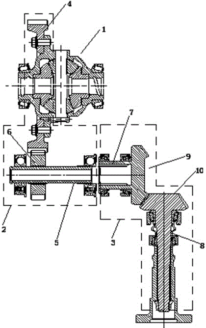
[0032] Example 1 A two-stage detachable power take-off

[0033] The present embodiment takes power from the transmission with differential 1 .

[0034] Such as figure 2 As shown, this embodiment includes a primary power take-off unit 2 and a secondary power take-off unit 3 , the power output end of the primary power take-off unit 2 and the power input end of the secondary power take-off unit 3 are coaxially linked. in:

[0035] (1) Primary power take-off unit 2

[0036] The primary power take-off unit 2 and the transmission are integrated in the first housing (not shown in the figure).

[0037] The primary power take-off unit 2 includes the ring gear of the differential 1 , that is, the differential ring gear 4 , an intermediate shaft 5 and a primary driven cylindrical gear 6 arranged on the intermediate shaft 5 . The primary driven cylindrical gear 6 meshes with the differential ring gear 4

[0038] The intermediate shaft 5 is arranged parallel to the central axis of th...

Embodiment 2

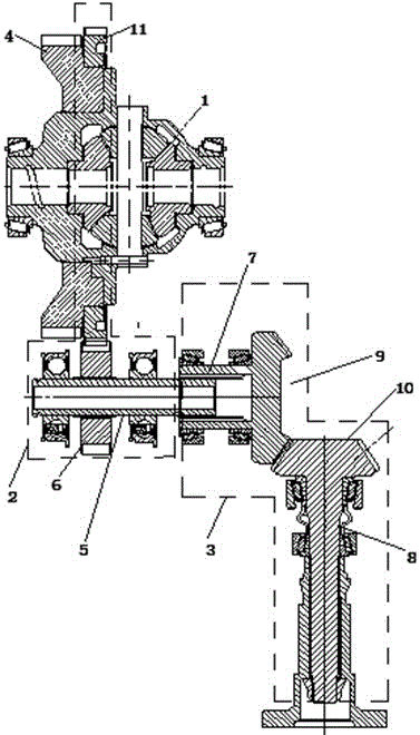
[0049] Embodiment 2 A two-stage detachable power take-off

[0050] The present embodiment takes power from the transmission with differential 1 .

[0051] Such as image 3 As shown, this embodiment includes a primary power take-off unit 2 and a secondary power take-off unit 3 , the power output end of the primary power take-off unit 2 and the power input end of the secondary power take-off unit 3 are coaxially linked. in:

[0052] (1) Primary power take-off unit 2

[0053] The primary power take-off unit 2 and the transmission are integrated in the first housing (not shown in the figure).

[0054]The primary power take-off unit 2 includes a linkage gear 11 arranged on the differential 1 , and also includes an intermediate shaft 5 and a primary driven cylindrical gear 6 arranged on the intermediate shaft 5 .

[0055] The intermediate shaft 5 is arranged parallel to the central axis of the differential ring gear 4, and is a hollow horizontal shaft. The left and right ends of...

Embodiment 3

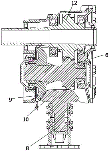
[0067] Embodiment 3 A two-stage detachable power take-off

[0068] The present embodiment takes power from the transmission with differential 1 .

[0069] Such as Figure 4 As shown, this embodiment includes a primary power take-off unit 2 and a secondary power take-off unit 3 , the power output end of the primary power take-off unit 2 and the power input end of the secondary power take-off unit 3 are coaxially linked. in:

[0070] (1) Primary power take-off unit 2

[0071] The primary power take-off unit 2 and the transmission are integrated in the first housing (not shown in the figure).

[0072] The primary power take-off unit 2 includes a primary driving cylindrical gear 12 set on the housing of the differential 1 and linked with the differential ring gear 4, and also includes an intermediate shaft 5 and a primary driven cylindrical gear arranged on the intermediate shaft 5. gear 6.

[0073] The intermediate shaft 5 is arranged parallel to the central axis of the diff...


PUM


Abstract

The invention provides a detachable two-stage power takeoff device which takes off power from a transmission provided with a differential. The detachable two-stage power takeoff device comprises a primary power takeoff unit and a secondary power takeoff unit, wherein the output end of the primary power takeoff unit is coaxially in linkage with the input end of the secondary power takeoff unit, the first power takeoff unit comprises a primary driving rotation member and a primary driven gear which are meshed with each other, and the primary driving rotation member is the differential of the transmission. Compared with the prior art, part quantity is decreased, the size of the power takeoff device is decreased, and accordingly an arrangement space is saved. In addition, a half shaft can be avoided, arrangement can be more flexible, and production cost can be reduced. The detachable two-stage power takeoff device is suitable for various transmissions provided with differentials and used for taking off power from the gear ring positions of the transmissions.

Description

technical field [0001] The invention relates to the technical field of power transmission and output mechanisms, in particular to a two-stage detachable power take-off. Background technique [0002] The power take-off device of the car is generally installed outside the gearbox, and the power is obtained through the differential case of the gearbox. The input shaft of the power take-off device is connected with the differential case of the gearbox, and the input gear is installed on the input shaft. [0003] The current dual-stage power take-off is powered by the differential case, and has many parts and a large volume, which cannot meet the space layout requirements of the vehicle. figure 1 Shown is an existing two-stage power take-off, the first-stage and second-stage power take-off units of the power take-off are both arranged in the power take-off housing, and the interior of the power take-off is composed of two horizontal shafts, a The root longitudinal axis, a pair ...

Claims


Application Information

Patent Timeline
Patent Type & Authority Patents(China)
IPC IPC(8): B60K25/06
Inventor 杨世卿谢立臣王一博梁磊章宏文
Owner GREAT WALL MOTOR CO LTD
Why Eureka
Try Eureka