Non-contact double-passage flow blocking device

A flow blocking device, non-contact technology, applied in valve device, valve operation/release device, multi-way valve, etc., can solve the problems of increasing pollution foreign matter, high labor cost, complex structure, etc., to improve work efficiency, Low production cost and good reliability

Active Publication Date: 2016-02-10
CHONGQING SKYFORBIO
View PDF4 Cites 2 Cited by
  • Summary
  • Abstract
  • Description
  • Claims
  • Application Information

AI Technical Summary

Problems solved by technology

[0004] 1. The structure is complex, difficult to clean, and the one-time cost is high (such as mechanical three-way and electromagnetic three-way valves);
[0005] 2. Due to the complex structure, the risk of pollution and foreign matter is greatly increased (such as mechanical three-way and electromagnetic three-way valves);
[0006] 3. Simple three-way and mechanical three-way by manual control, low efficiency and high labor cost

Method used


Image

  • Non-contact double-passage flow blocking device
  • Non-contact double-passage flow blocking device
  • Non-contact double-passage flow blocking device

Examples


Embodiment 1

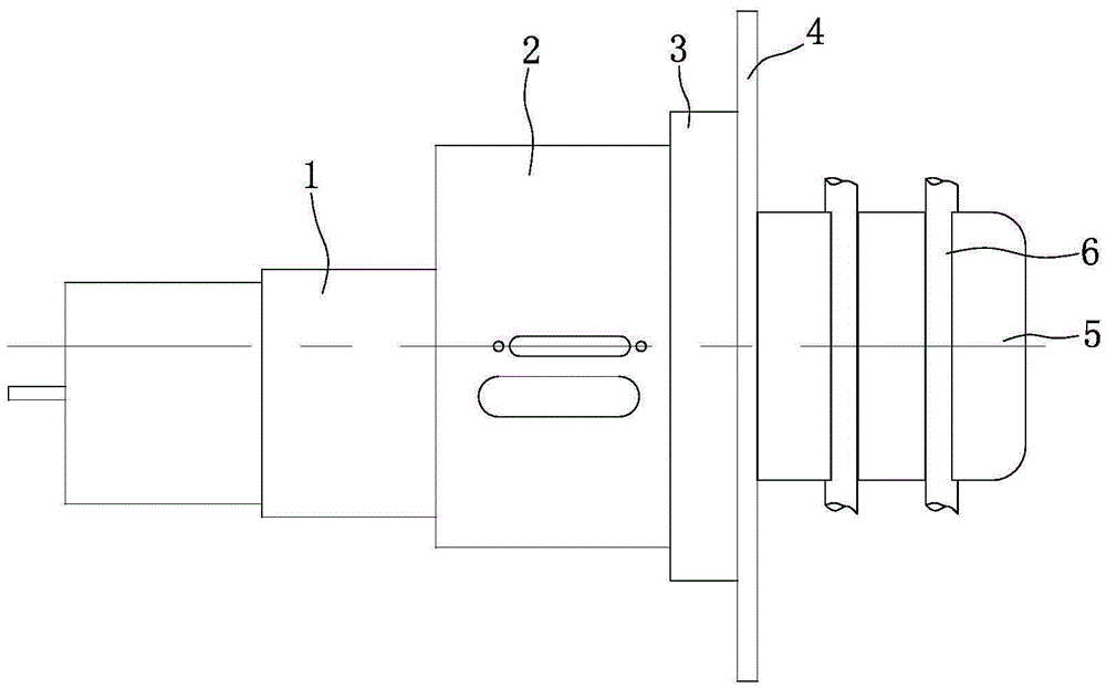
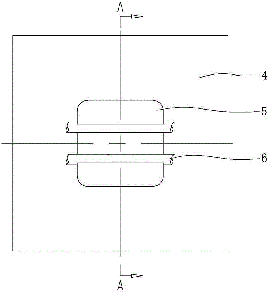
[0036] Such as figure 1 , figure 2 As shown, the housing 5 is located outside the box 4, and the housing 5 is preferably injection molded. An annular boss is integrally formed on the casing 5, and the annular boss extends into the box body 4, and the casing 5 is fixed to the box body 4 by a plurality of screws. On the top of the casing 5 are provided two locking grooves 5a for locking the pipeline 6 side by side, and the two locking grooves 5a are parallel to each other. The slot 5a is a through slot, and the bottom of the slot 5a communicates with the inner cavity 5b of the housing 5; the cross section of the bottom of the slot 5a is preferably circular, and the diameter of the bottom of the slot 5a is larger than the width of the notch.

[0037] Such as figure 1 , figure 2As shown, a fixed plate 3 is provided at a position corresponding to the outer shell 5 in the box body 4. The fixed plate 3 is a rectangular flat plate structure, and through injection molding, the fi...

Embodiment 2

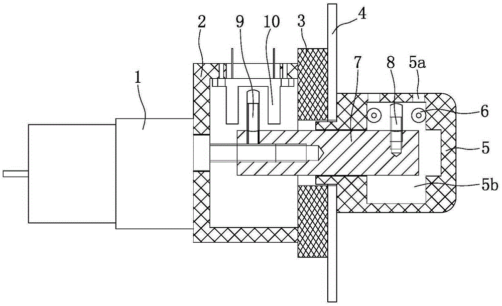
[0042] Such as image 3 , Figure 4 , Figure 5 , Figure 6 , Figure 7 As shown, two upper and lower locking grooves 5a parallel to each other are provided on the end surface of the housing 5 . The shaft coupling 7 is a cylinder, and the inner end of the shaft coupling 7 is inserted into the output shaft of the motor 1, and is tightened by radially threaded screws. Pin 9 is also installed at the inner end of shaft coupling 7, and this pin 9 is perpendicular to shaft coupling 7, and three position sensors 10 that inductively cooperate with pin 9 are fixed on the inner wall of motor fixed block 2, and these three position sensors 10 are in On the same circle, two of the position sensors 10 are located on a straight line, and the two position sensors 10 are perpendicular to the other position sensor 10 . The outer end of the shaft coupling 7 extends into the inner cavity 5b of the housing 5, and a blocking device is integrally formed at the outer end of the shaft coupling 7...

Embodiment 3

[0047] Such as Figure 8 and combine image 3 , Figure 4 , Figure 5 , Figure 6 As shown, a blocking device is integrally formed at the outer end of the coupling 7, and the blocking device is Shaped blocking briquetting block 12. The blocking briquetting block 12 is made up of a transverse section and a longitudinal section, the transverse section is perpendicular to the longitudinal section, the middle part of the transverse section is integrated with the end of the longitudinal section, and the center of the transverse section is located on the axis of the shaft coupling 7 . The length of the transverse section is equal to the diameter of the shaft coupling 7, the length of the longitudinal section is half of the length of the transverse section, and the ends of the transverse section and the longitudinal section are rounded.

[0048] The rest of the structure of this embodiment is the same as that of Embodiment 2, and will not be repeated here.

[0049] The working...


PUM


Abstract

The invention discloses a non-contact double-passage flow blocking device. A housing is disposed outside a box and fixed to the box. The housing is provided with two locking slots side by side for locking pipelines. The groove bottoms of the locking sots are communicated with an inner cavity of the housing. The box is internally provided with a fixing plate corresponding to the housing in position. A motor fixing block is mounted on the fixing plate. A motor is mounted on the motor fixing block. An output shaft of the motor extends into the motor fixing block and is connected with the inner end of a coupling. The outer end of the coupling extends into the inner cavity of the housing, and a blocking device for controlling connection and disconnection of two pipelines is disposed at the outer end of the coupling. The non-contact double-passage flow blocking device is simple and compact in structure, low in production cost, small in size and good in reliability, and operating efficiency can be effectively improved; a control portion does not contact a liquid or gas controlled, the risk of pollution and foreign matters is substantially reduced, and reusing is facilitated.

Description

technical field [0001] The invention belongs to the fields of medical equipment and instrument analysis, and in particular relates to a non-contact dual-channel flow blocking device. Background technique [0002] The three-way device is a two-channel flow blocking device, which is a commonly used device in the field of medical equipment and instrument analysis. It is mainly used to control the flow direction of liquid or gas, or to control the opening and blocking of a certain flow direction. Such as: selective delivery of more than one liquid such as clinical infusion, flushing device, analytical instrument, etc., as well as flushing and suction of cavities such as clinical operations, trauma wounds and gastrointestinal tract, etc. The main types of its three-way device are: simple three-way that is manually blocked, mechanical three-way that is manually adjusted, mechanical three-way that is controlled by pressure, and a solenoid valve that is controlled by electricity. ...

Claims


Application Information

Patent Timeline
Patent Type & Authority Applications(China)
IPC IPC(8): A61M5/172A61M3/02A61M39/22F16K31/04F16K11/02F16K7/02
Inventor 王国华王永贤龙洪伟李侠王哲西
Owner CHONGQING SKYFORBIO
Why Eureka
Try Eureka