
Winch
A hoist and reel technology, applied in the direction of hoisting devices, spring mechanisms, etc., can solve the problems that the steel wire rope or safety rope cannot be used as a hanging basket, the wire rope at the end is damaged and broken, and the brake and parking device is prone to failure.
Patent Information
- Authority / Receiving Office
- CN · China
- Patent Type
- Applications(China)
- Current Assignee / Owner
- Publication Date
- 2016-02-17
Smart Images
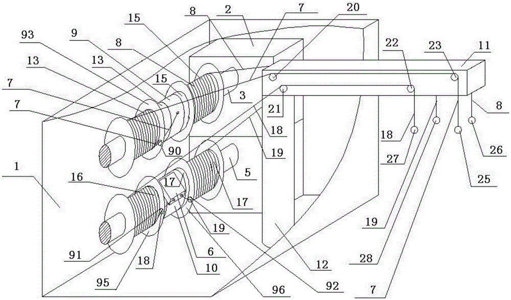
Figure 1 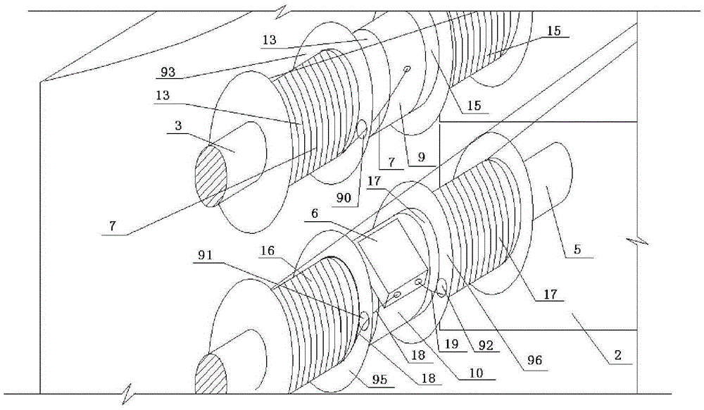
Figure 2 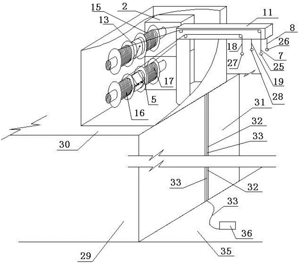
Figure 3
Abstract
Description
technical field
[0001] This application belongs to a lifting device. Background technique
[0002] The main function of the existing lifting equipment such as the hoist is to lift and pull the heavy object to go up or down. If it hovers in the air, it depends on the braking device of the reel to stop. The existing regulations require that the wire rope of the hoist cannot be pulled completely. It must be ensured that the steel wire rope coiled on the drum is kept for at least 3 turns to ensure the safety of the stress-bearing end. If all the steel wire rope coiled on the drum is released, the steel wire rope will be fixed and connected to the pressure plate on the drum through the pressure plate. And the anchor bolts are very vulnerable to the radial tension, and they are peeled off the reel one by one to cause danger. It is precisely because of the above reasons that the steel wire rope extending from the fixed end of the wire rope is at least wound on the reel and retained...
Examples
Embodiment Construction
[0088] like figure 1 as shown, figure 1 It is a schematic oblique view of the winch according to the first embodiment of the present application. The hoist includes a housing 1, a motor 2, a rotating shaft 3, a rotating shaft 5, a descender 6, a stay rope 7, a stay rope 8, a connecting end support 9, a connecting end support 10, a cantilever 11, and a column 12. The motor 2, the rotating shaft 3, the rotating shaft 5, the descending device 6, the pull rope 7, the pull rope 8, the connection end support 9, the connection end support 10, and the column 12 are arranged in the housing, and the motor 2 Connecting with the rotating shaft 3 and the rotating shaft 5 can drive the rotating shaft 3 and the rotating shaft 5 to rotate. The above-mentioned connecting end support 9 is the outer ring of the one-way bearing, and the inner ring of the above-mentioned one-way bearing is fixedly connected with the rotating shaft 3. The above-mentioned The connecting end support 9 is set on the...