
Multiple-blade closed air valve
A multi-blade, air valve technology, applied in the direction of lift valve, valve device, engine components, etc., can solve the problems of difficult sealing, hidden leakage, leakage, etc., and achieve the effect of solving difficult sealing and good sealing effect.
- Summary
- Abstract
- Description
- Claims
- Application Information
AI Technical Summary
Problems solved by technology
Method used
Image

Examples
Embodiment Construction
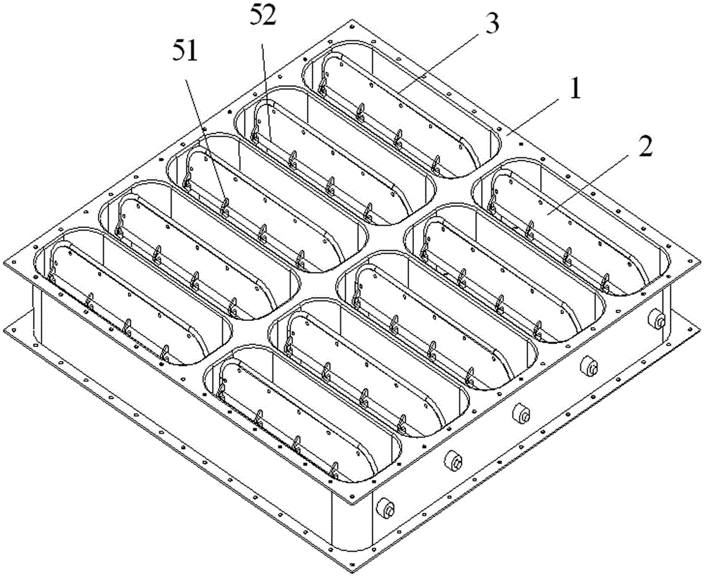
[0024] The following combination Figure 2 ~ Figure 6 , a preferred embodiment of the present invention is described in detail.
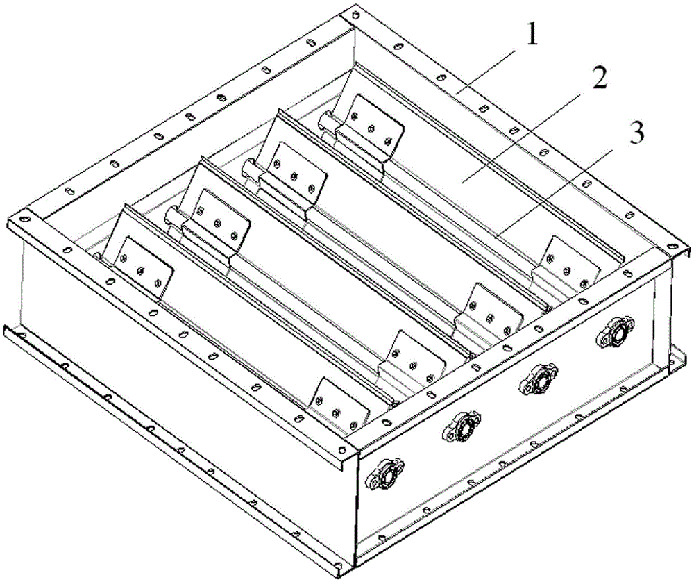
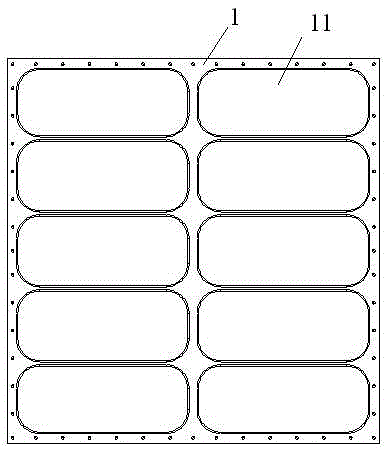
[0025] Such as figure 2 As shown, the multi-blade airtight air valve provided by the present invention includes: a square valve body 1, such as image 3 As shown, there are multiple rows of openings 11 arranged in sequence, and the end points of each opening 11 are arranged in a circular arc shape; a plurality of blades 2, each blade 2 is correspondingly arranged in each opening 11 through the first fixing assembly , and the end point of each blade 2 is arranged in an arc shape, matching the opening 11; the sealing ring 3, such as Figure 4 As shown, it is surrounded by a plurality of second fixing components on the outside of the vane 2 and is in contact with the inner wall of the square valve body 1 .
[0026] Such as Figure 5 As shown, the second fixing component includes: an upper clamping plate 41, which is covered and arranged on the upp...
PUM
 Abstract
Description
Claims
Application Information