
An assembly structure used for a push type dental high-speed turbine handpiece and a spindle assembly
An assembly structure, pressing technology, applied in the direction of dentistry, dental drilling, dental tools, etc., can solve the problems of affecting the clamping and replacement of burs, hidden dangers, small size, etc., to achieve convenient clamping and replacement, and force application. Accurate and stable effect with large pressure area
- Summary
- Abstract
- Description
- Claims
- Application Information
AI Technical Summary
Problems solved by technology
Method used
Image

Examples
Embodiment Construction
[0022] The technical solutions of the present invention will be further described below in conjunction with the accompanying drawings and through specific implementation methods.
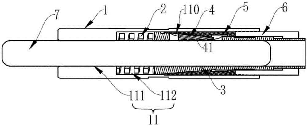
[0023] Such as figure 1 and figure 2 As shown, a shaft assembly of a press-type dental high-speed turbine handpiece includes a shaft 1, a hollow cavity 11 is provided inside along the axial direction of the shaft 1, and a spring 2 and a chuck body 3 are provided from It is slidably arranged in the hollow cavity 11 from left to right; the hollow cavity 11 is provided with a mounting cone surface 110, and the inner diameter of the mounting cone surface 110 gradually decreases from left to right;
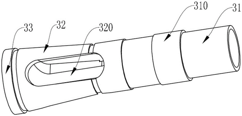
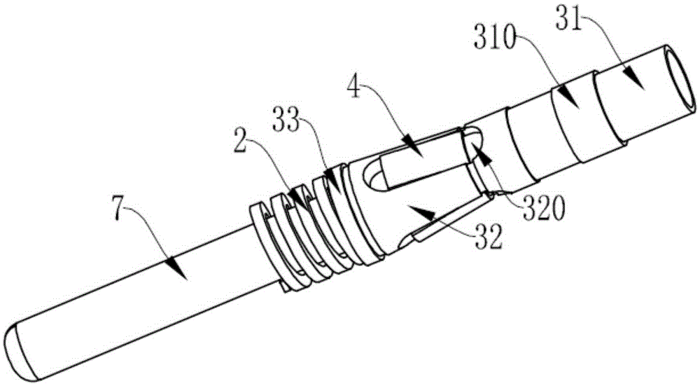
[0024] The chuck body 3 is a hollow structure composed of a pressing part 31, a clamping cone 32 and a bottom ring 33. The pressing part 31 is formed by the small end of the clamping cone 32 along the Axially extending to the right, the bottom ring 33 is formed by extending the large end of the clamping c...
PUM
 Abstract
Description
Claims
Application Information