Continuous casting blank section casting cold material placing structure and placing method thereof

A continuous casting slab and cold material technology, which is applied to the placement structure of the continuous casting slab section and its placement field, and can solve the problem of continuous casting slab dragging, leakage, large economic losses, production accidents, leakage, etc. question

Inactive Publication Date: 2016-03-30
WUHU XINXING DUCTILE IRON PIPES
View PDF9 Cites 6 Cited by
  • Summary
  • Abstract
  • Description
  • Claims
  • Application Information

AI Technical Summary

Problems solved by technology

[0002] At present, the continuous casting process adopts welding cold material for the placement structure of the medium and large continuous casting slab section, and welds the steel plate in the middle of the cold material frame as the main component of the cold material, which is very important for the crystallizer. If the cross-section of the billet and the round billet are large, if they are placed in this way, the center temperature of the continuous casting billet will be too high during the pouring process, resulting in leakage accidents, and at the same time, the continuous casting billet will be dragged, Leakage, resulting in large economic losses and production accidents

Method used


Image

  • Continuous casting blank section casting cold material placing structure and placing method thereof
  • Continuous casting blank section casting cold material placing structure and placing method thereof
  • Continuous casting blank section casting cold material placing structure and placing method thereof

Examples


Embodiment Construction

[0030] Specific embodiments of the present invention will be described in detail below in conjunction with the accompanying drawings. It should be understood that the specific embodiments described here are only used to illustrate and explain the present invention, not to limit the present invention.

[0031] In the present invention, in the absence of a contrary statement, the orientation words included in the term such as "up, down, left, right, inside, outside" only represent the orientation of the term in the normal use state, or for the purpose of A common term understood by those skilled in the art, and should not be considered as a limitation of the term.

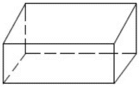
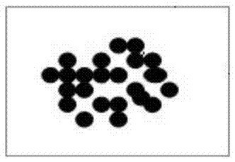
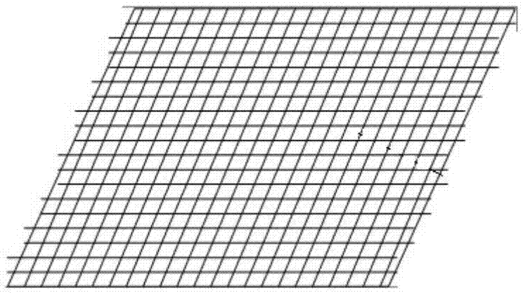
[0032] The invention provides a placement structure for the cold material poured on the end face of the continuous casting slab, such as figure 1 , figure 2 , image 3 , Figure 4 and Figure 5 As shown, the placement structure includes a crystallizer 3, a dummy head arranged inside the crystallizer 3, and the ...


PUM


Abstract

The invention discloses a continuous casting blank section casting cold material placing structure and a placing method thereof. The placing structure comprises a crystallizer, a dummy bar head arranged in the crystallizer, and the following parts arranged in sequence in the vertical direction from bottom to top: asbestos cloth, multiple steel wire shots and casting bricks; multiple asbestos ropes are filled in a gap between the crystallizer and the dummy bar head; the asbestos cloth respectively covers the upper surface of the dummy bar head and the multiple asbestos ropes; the casting bricks are coated with cold material frames; multiple reinforcements are arranged on the top surfaces of the cold material frames; and the multiple steel wire shots cover the asbestos cloth. The placing structure can reduce the economic loss in the casting process, and can prevent production accidents caused by overhigh center temperature of continuous casting blanks.

Description

technical field [0001] The invention relates to a continuous casting production technology, in particular to a placement structure and a placement method for continuous casting slab cross-section pouring cold material. Background technique [0002] At present, the continuous casting process adopts welding cold material for the placement structure of the medium and large continuous casting slab section, and welds the steel plate in the middle of the cold material frame as the main component of the cold material, which is very important for the crystallizer. If the cross-section of the billet and the round billet are large, if they are placed in this way, the center temperature of the continuous casting billet will be too high during the pouring process, resulting in leakage accidents, and at the same time, the continuous casting billet will be dragged, Leakage, resulting in greater economic losses and production accidents. [0003] Therefore, it is an urgent problem to be so...

Claims


Application Information

Patent Timeline
Patent Type & Authority Applications(China)
IPC IPC(8): B22D11/08
CPCB22D11/08B22D11/085
Inventor 刘志勇刘光绪孙华莹
Owner WUHU XINXING DUCTILE IRON PIPES
Why Eureka
Try Eureka