Connecting inserting rod, connecting joint device and pre-stressed prefabricated part

A technology for connecting joints and prefabricated parts, applied in the direction of connecting members, rod connections, sheet pile walls, etc., can solve the problems affecting the reliability of the pile body connection, the plug cannot be inserted in place, the plug is difficult to enter the buckle cylinder, etc. The connection process is stable and reliable, the effect of avoiding the drop of the pull-out resistance and the damage of the stress is avoided.

Inactive Publication Date: 2019-06-11
周兆弟
View PDF2 Cites 2 Cited by
  • Summary
  • Abstract
  • Description
  • Claims
  • Application Information

AI Technical Summary

Problems solved by technology

However, since the deformation of the buckle barrel is weaker than that of the split tapered sleeve, the pin needs to be adaptively improved, otherwise it will be relatively difficult for the pin to enter the buckle barrel
Specifically, the latch of this structure is engaged with the card-type card table of the button barrel, and the guide part of the latch is a straight cut, and the guiding effect is not ideal. During the insertion process, the latch may be stuck with the card table, so that some latches cannot be inserted into place. , thus affecting the reliability of the pile connection, resulting in a decrease in pull-out and tensile capacity

Method used


Image

  • Connecting inserting rod, connecting joint device and pre-stressed prefabricated part
  • Connecting inserting rod, connecting joint device and pre-stressed prefabricated part
  • Connecting inserting rod, connecting joint device and pre-stressed prefabricated part

Examples


Embodiment 1

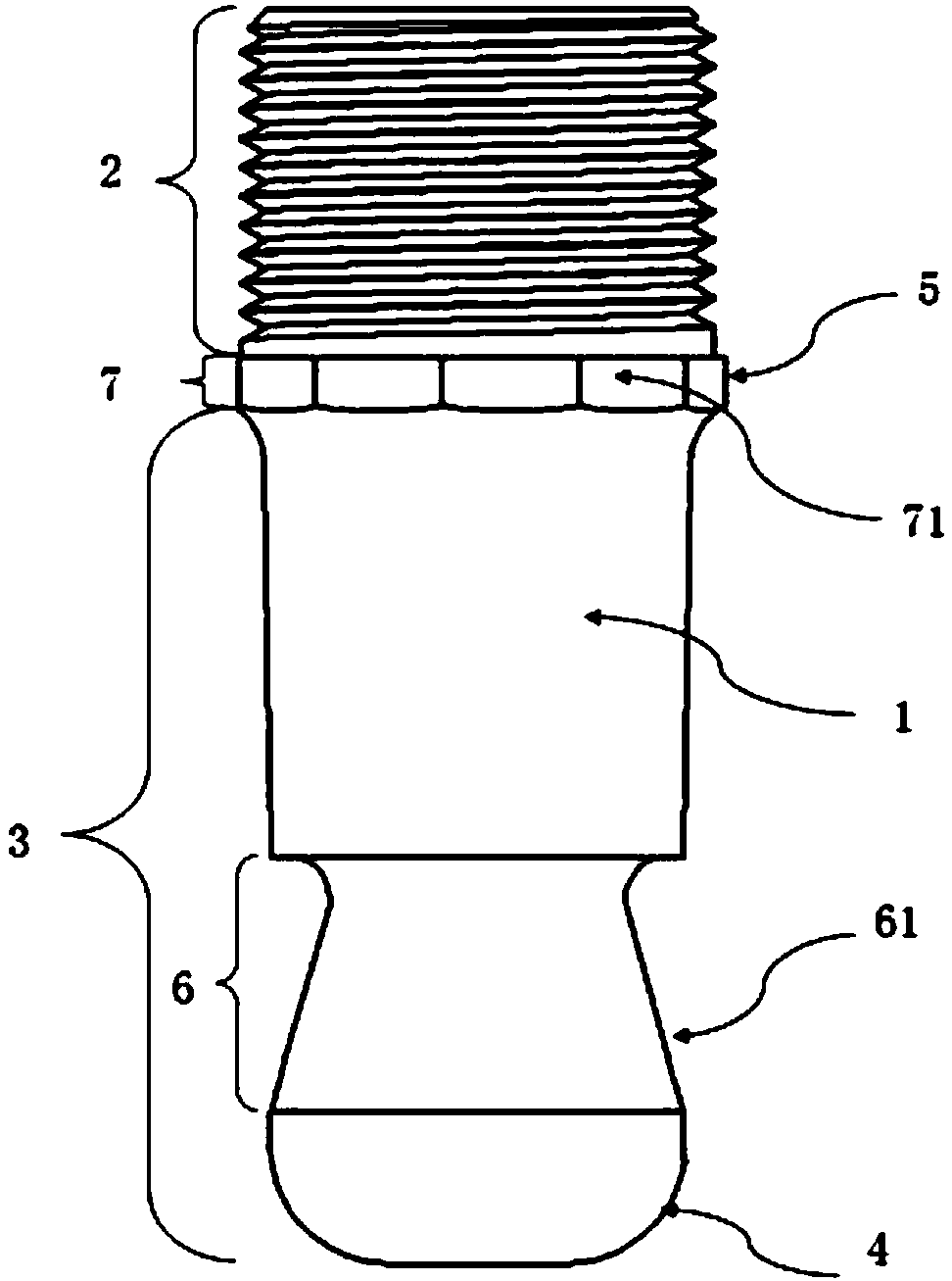
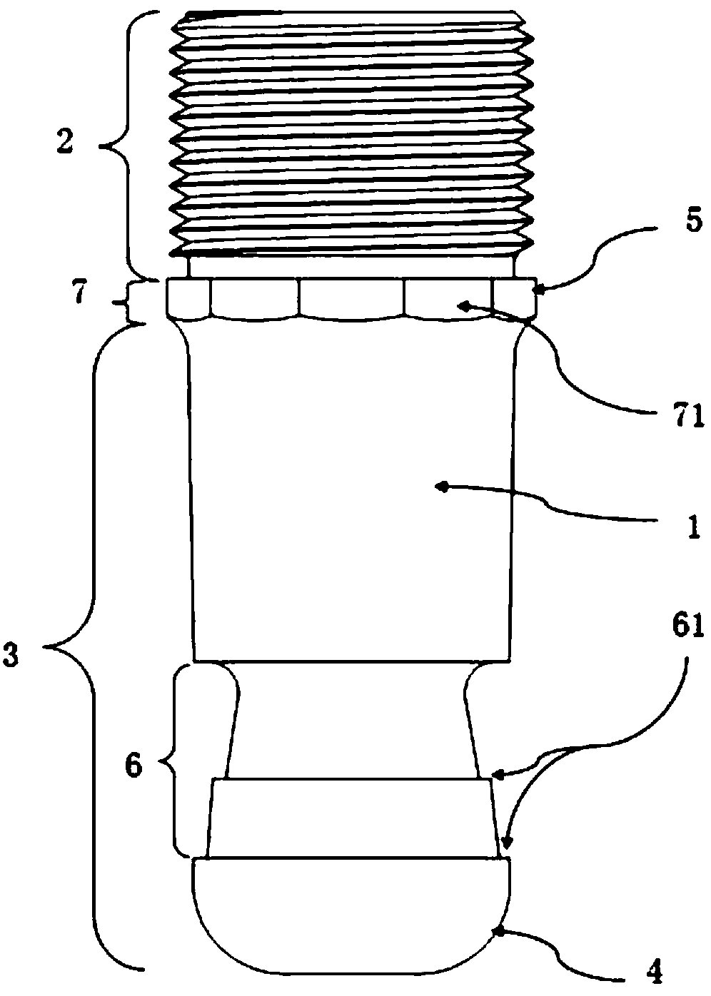
[0056] Such as figure 1 Shown is a schematic diagram of the first embodiment of the connecting rod of the present invention. A connecting rod includes a rod body 1. The rod body 1 includes a connecting part 2 and a plugging part 3. The end of the plugging part 3 is provided with a buckle with the outside. The barrel forms a clamping joint with limited fit, wherein the end of the clamping joint close to the connecting part is provided with a limit surface 61 of the clamping buckle barrel, and the end of the clamping joint far away from the connecting part is provided with a guide surface 4, and at least part of the guide surface 4 is On the arc surface, the connecting part 2 is provided with a screw thread, and the insertion part 3 is a tapered body extending from the connection part 2 and gradually becomes smaller, and the end of the insertion part 3 is provided with an arc-shaped guide surface 4. It can be understood that The connecting rod can also be a cylinder or other reg...

Embodiment 2

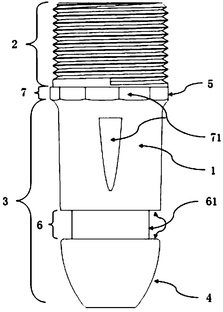
[0066] Such as Figure 4 The schematic diagram of the structure of the connecting joint device of the present invention is shown. In this embodiment, the connecting rod adopts figure 2 The shown connecting rod includes a buckle barrel 105 and the described connecting rod, wherein one end of the buckle barrel 105 is provided with at least two pieces of cards 152 for inserting the snap joints of the connecting rod and forming a snap-fit. The button cylinder 105 is provided with a second guide surface 40 at the first contact portion connecting the plunger, and the button cylinder 105 includes a cylinder body and a plurality of card platforms 152 with a buckle function on the cylinder body, and the plurality of card platforms 152 are surrounded by Arranged at uniform intervals, in this embodiment, the cylinder includes a bottom bracket 151 and a connecting piece 153, the card table 152 and the bottom bracket 151 are connected through the connecting piece 153, and the connecting p...

Embodiment 3

[0075] Such as Figure 6 Shown is a schematic diagram of the structure of the buckle barrel of the connecting joint device of the present invention. The outer periphery of the barrel including the buckle barrel 105 is provided with a screw thread, and the clamping platform shrinks radially toward the axial direction. At this time, the buckle barrel is the same as that in Embodiment 3. The barrel structure is different. The barrel can be regarded as an extension that stabilizes the card tables set at intervals together. It does not need to be divided into a base and a connecting piece, because the barrel and the card tables are cast as one piece, such as a circular cylinder. , the card table shrinks radially toward the axis, which can be understood as the card table is bent inward to form a tapered sleeve that gradually becomes smaller.

[0076] In further refinement, when processing threaded buttons, in order to facilitate processing, there will be an undercut at the tail of t...


PUM


Abstract

The invention provides a connecting inserting rod, a connecting joint device and a pre-stressed prefabricated part applying the connecting joint. The connecting inserting rod is simple in structure, firm in connection and convenient to install. The connecting inserting rod comprises a rod body, wherein the rod body comprises a connecting part and an inserting part, the end of the inserting part isprovided with a clamping joint which is matched with an outer buckling barrel in a limiting mode, a guide surface is arranged at one end of the clamping joint, at least part of the guide surface is an arc surface, at least two clamping tables are arranged at one end of the buckling barrel and are inserted into the buckling barrel and are in clamping connection with each other, and a plurality ofconnecting joint devices are uniformly and correspondingly arranged between an upper pre-stress prefabricated part and a lower pre-stress prefabricated part. The guide part of the connecting insertingrod is an arc surface, the contact surface of the guide part and the buckling barrel clamping tables is a circular surface, and the contact surfaces in the guide process are free of dead corners andcannot be clamped, so that the insertion of bolts in place is guaranteed, and the connection reliability of a pile body is improved.

Description

[0001] This application is a divisional application for an invention titled "A Connecting Insertion Rod, Connecting Joint Device, and Prestressed Prefabricated Part". Its filing date is: 2017-12-04, and its application number is: 2017112625178. technical field [0002] The invention relates to the technical field of building connectors, in particular to a connecting insert rod, a connecting joint device and a prestressed prefabricated part comprising the connecting joint device. Background technique [0003] At present, most of the prefabricated piles used in building foundation uplift engineering adopt the form of end plate welding to connect piles with piles. Since this connection method belongs to electric welding, due to the uneven welding level of personnel, there may be certain potential safety hazards, which will affect the construction quality. For this reason, many inventors improve the connection mode of piles to the direction of no end plate. [0004] For example...

Claims


Application Information

Patent Timeline
Patent Type & Authority Applications(China)
IPC IPC(8): F16B7/02F16B7/18E02D5/24
Inventor 周兆弟
Owner 周兆弟
Why Eureka
Try Eureka