Connector device and pre-stressed prefabricated piece

A technology for connecting joints and prefabricated parts, used in construction, sheet pile walls, infrastructure engineering and other directions, can solve the problems of high processing difficulty and cost of buckle cylinders, reduced pull-out and tensile capacity, and high firmness and hardness of elastic sheets. Achieve the effect of avoiding the drop of pullout resistance, avoiding stress damage, and improving reliability.

Inactive Publication Date: 2018-08-17
周兆弟
View PDF0 Cites 2 Cited by
  • Summary
  • Abstract
  • Description
  • Claims
  • Application Information

AI Technical Summary

Problems solved by technology

However, the buckle barrel is composed of the bottom bracket and the card connected by the elastic sheet, and the material requirements of the card, the bottom bracket and the elastic sheet are different, because the card and the insertion rod need to bear the pull-out force, so the material hardness is required to be very high during design, and The base bracket and the elastic sheet do not have high hardness requirements, but the elastic sheet has toughness design requirements, and the card usually needs special quenching treatment. The physical properties such as toughness are different, and the processing difficulty and cost of the entire buckle barrel are very high. The usual practice is to uniformly process the entire buckle barrel according to the design requirements of the card. The lever cannot prop up the deck
[0005] In this way, when the connecting joint device is actually used, due to the high firmness and hardness of the elas

Method used


Image

  • Connector device and pre-stressed prefabricated piece
  • Connector device and pre-stressed prefabricated piece
  • Connector device and pre-stressed prefabricated piece

Examples


Example Embodiment

[0029] Example 1

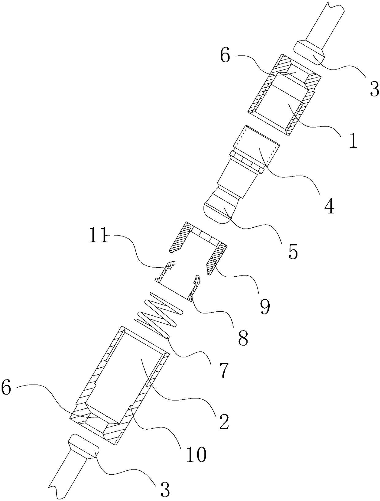
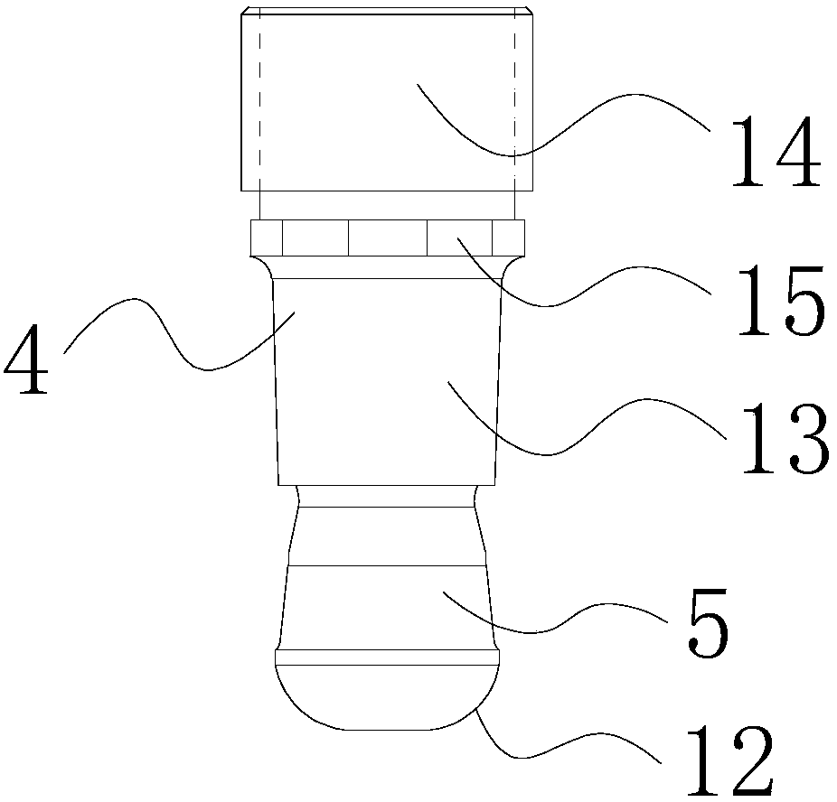
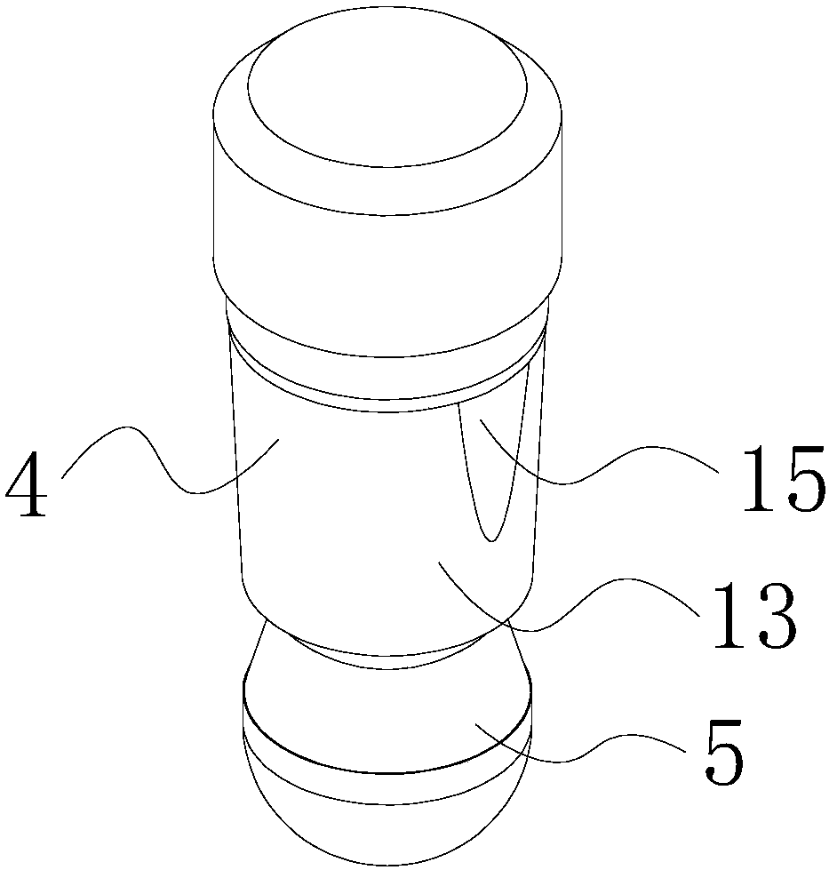
[0030] Such as figure 1 As shown, the present invention provides a connecting joint device, including an upper section nut 1 and a lower section nut 2. The bottoms of the upper section nut 1 and the lower section nut 2 are both provided with a rib hole 6 for clamping with the rigid expansion head 3. , The end of the upper section nut 1 away from the rib hole 6 is threadedly connected with a plunger 4, the plunger 4 is provided with a plug connector 5, and the lower section nut 2 is away from the rib hole 6 and is sequentially provided with an elastic element 7, a buckle 8 and a limit nut 9. The buckle cylinder 8 is provided with a clamping table 11, wherein the inner cavity of the lower section nut 2 is provided with a limit table 10, which limits the displacement of the buckle cylinder 8 in the direction of the rib hole 6 to make the insertion The joint 5 expands the clamping table 11 on the buckle cylinder 8 and inserts the largest part 16 of the joint into t...

Example Embodiment

[0039] Example 2

[0040] Such as Figure 8 As shown, the present invention also discloses a prestressed preform, including a first prestressed preform 20, a second prestressed preform 21, and used to connect the first prestressed preform 20 and the second prestressed The connection joint device of the preform 21, the end faces of the first prestressed preform 20 and the second prestressed preform 21 are equal in size, and the interfaces are opposite. The connection joint device is the connection joint device of embodiment 1, wherein the prestressed preform Several longitudinal ribs 22 and transverse ribs in the part constitute the rigid framework of the preform. The longitudinal ribs 22 are generally uniformly arranged in regular patterns such as round or square in the prestressed preform. Both ends of the longitudinal ribs 22 of the prestressed preform They are made into rigid enlarged heads 3 respectively, and are connected to the upper section nut 1 and the lower section nut...


PUM


Abstract

The invention provides a connector device which is simple in structure, safe and reliable. The connector device comprises an upper nut and a lower nut. The bottom of the upper nut and the bottom of the lower nut are both provided with rib insertion holes used for being connected with a rigid expansion head in a clamped manner. The end, far away from the corresponding rib insertion hole, of the upper nut is connected with an insertion rod in a threaded manner. The insertion rod is provided with an insertion connection head. The side, far away from the rib insertion holes, of the lower nut is sequentially provided with an elastic element, a buckle cylinder and limiting nuts. The inner cavity of the lower nut is provided with a limiting platform. The limiting platform limits the displacement,towards the rib insertion holes, of the buckle cylinder, so that the insertion connection head opens a clamping platform, and the biggest part of the insertion connection head passes through the smallest portion of the clamping platform. The problem that due to the material texture, the insertion rod cannot open the clamping platform, and connection is instable is avoided.

Description

technical field [0001] The invention relates to the technical field of building connectors, in particular to a connecting joint device and a prestressed prefabricated part comprising the connecting joint device. Background technique [0002] At present, most of the prefabricated piles used in building foundation uplift engineering adopt the form of end plate welding to connect piles with piles. Since this connection method belongs to electric welding, due to the uneven welding level of personnel, there may be certain potential safety hazards, which will affect the construction quality. For this reason, many enterprises have improved the connection method of piles to the direction of no end plate. [0003] For example, the literature retrieved by the applicant discloses a buckle cylinder, which includes a ring-shaped base, and a plurality of card structures with buckle functions are arranged at intervals along the circumferential direction on the base. On this basis, a conn...

Claims


Application Information

Patent Timeline
IPC IPC(8): E02D5/22E02D5/52
CPCE02D5/22E02D5/52
Inventor 周兆弟
Owner 周兆弟
Why Eureka
Try Eureka