Connecting inserting rod, connecting joint devices and prestress prefabricated parts
A technology for inserting rods and connecting parts, which is applied in the direction of connecting members, rods, and sheet pile walls, etc. It can solve the problems affecting the reliability of the pile body connection, the plug cannot be inserted in place, and it is difficult for the plug to enter the buckle barrel. The connection process is stable and reliable, avoiding the decline of pull-out and tensile capacity, and avoiding the effect of stress damage
- Summary
- Abstract
- Description
- Claims
- Application Information
AI Technical Summary
Problems solved by technology
Method used
Image
Examples
Embodiment 1
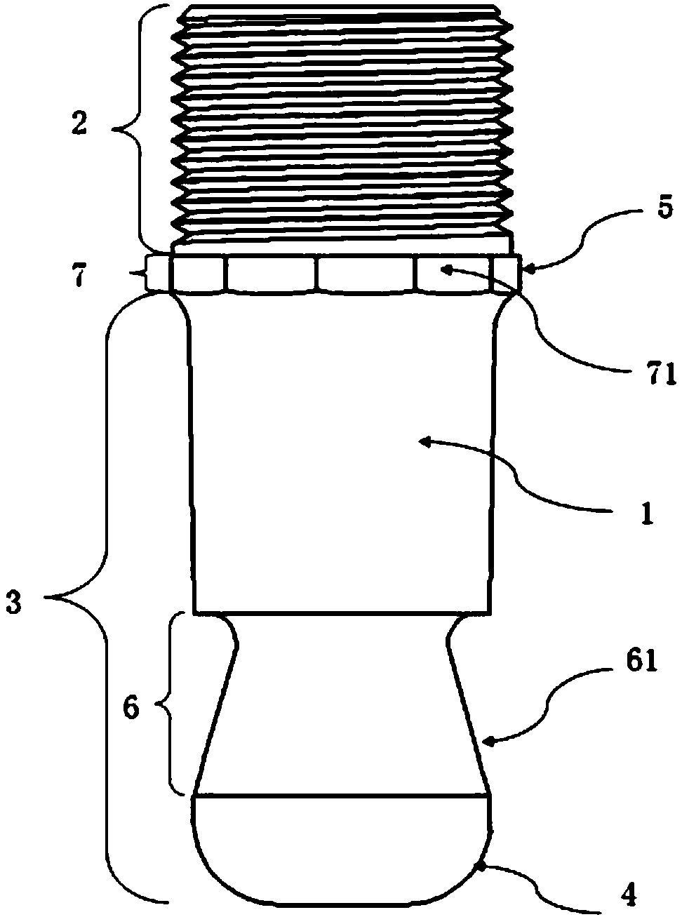
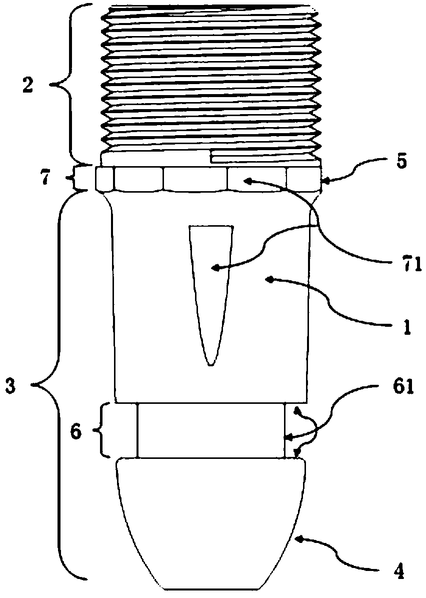
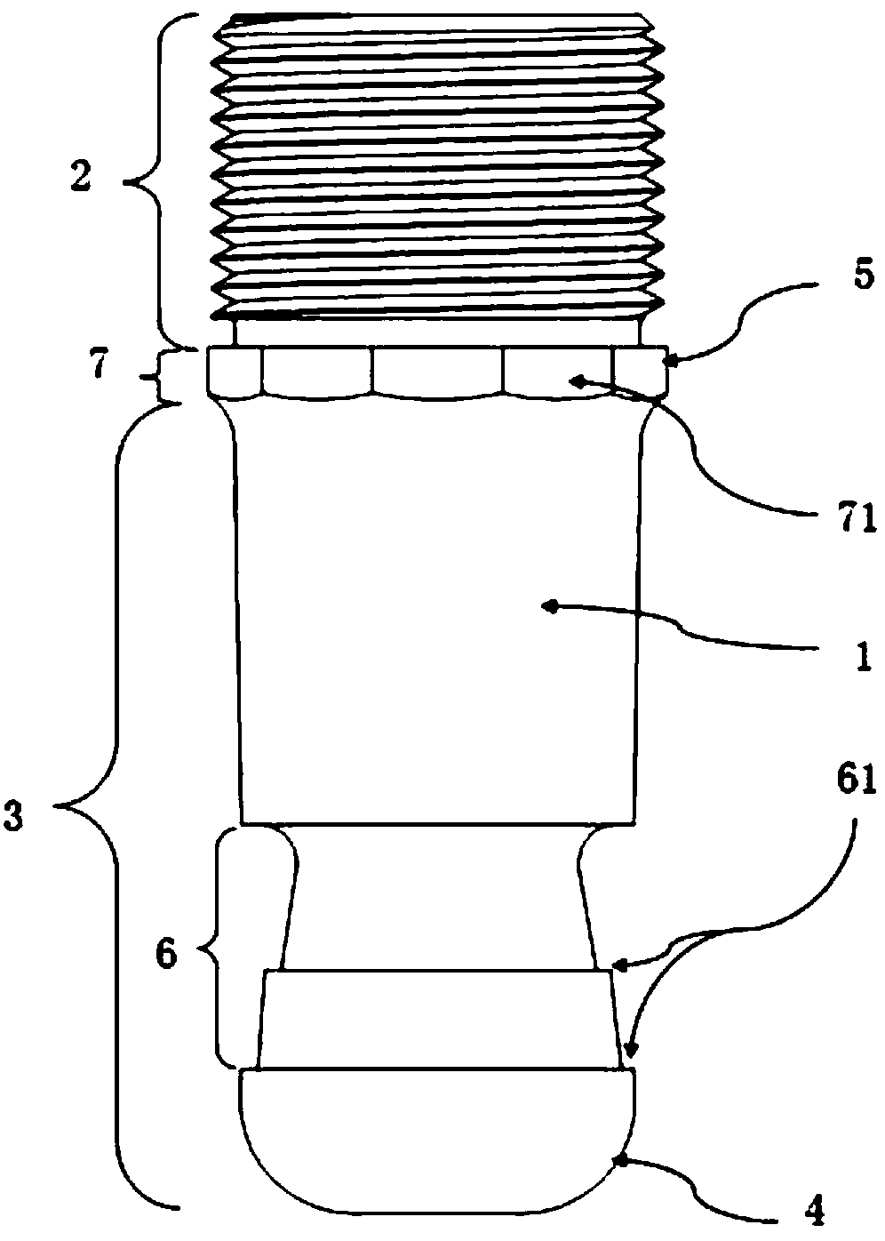
[0056] Such as figure 1 Shown is a schematic diagram of the first embodiment of the connecting rod of the present invention. A connecting rod includes a rod body 1. The rod body 1 includes a connecting part 2 and a plugging part 3. The end of the plugging part 3 is provided with a buckle with the outside. The barrel forms a clamping joint with limited fit, wherein the end of the clamping joint close to the connecting part is provided with a limit surface 61 of the clamping buckle barrel, and the end of the clamping joint far away from the connecting part is provided with a guide surface 4, and at least part of the guide surface 4 is On the arc surface, the connecting part 2 is provided with a screw thread, and the insertion part 3 is a tapered body extending from the connection part 2 and gradually becomes smaller, and the end of the insertion part 3 is provided with an arc-shaped guide surface 4. It can be understood that The connecting rod can also be a cylinder or other reg...
Embodiment 2
[0066] Such as Figure 4 The schematic diagram of the structure of the connecting joint device of the present invention is shown. In this embodiment, the connecting rod adopts figure 2 The shown connecting rod includes a buckle barrel 105 and the described connecting rod, wherein one end of the buckle barrel 105 is provided with at least two pieces of cards 152 for inserting the snap joints of the connecting rod and forming a snap-fit. The button cylinder 105 is provided with a second guide surface 40 at the first contact portion connecting the plunger, and the button cylinder 105 includes a cylinder body and a plurality of card platforms 152 with a buckle function on the cylinder body, and the plurality of card platforms 152 are surrounded by Arranged at uniform intervals, in this embodiment, the cylinder includes a bottom bracket 151 and a connecting piece 153, the card table 152 and the bottom bracket 151 are connected through the connecting piece 153, and the connecting p...
Embodiment 3
[0075] Such as Image 6 Shown is a schematic diagram of the structure of the buckle barrel of the connecting joint device of the present invention. The outer periphery of the barrel including the buckle barrel 105 is provided with a screw thread, and the clamping platform shrinks radially toward the axial direction. At this time, the buckle barrel is the same as that in Embodiment 3. The barrel structure is different. The barrel can be regarded as an extension that stabilizes the card tables set at intervals together. It does not need to be divided into a base and a connecting piece, because the barrel and the card tables are cast as one piece, such as a circular cylinder. , the card table shrinks radially toward the axis, which can be understood as the card table is bent inward to form a tapered sleeve that gradually becomes smaller.
[0076] In further refinement, when processing threaded buttons, in order to facilitate processing, there will be an undercut at the tail of th...
PUM
 Abstract
Description
Claims
Application Information
 - R&D
- Intellectual Property
- Life Sciences
- Materials
- Tech Scout
- Unparalleled Data Quality
- Higher Quality Content
- 60% Fewer Hallucinations
Browse by: Latest US Patents, China's latest patents, Technical Efficacy Thesaurus, Application Domain, Technology Topic, Popular Technical Reports.
© 2025 PatSnap. All rights reserved.Legal|Privacy policy|Modern Slavery Act Transparency Statement|Sitemap|About US| Contact US: help@patsnap.com


