A connector and its use method, electronic equipment provided with the connector
A technology for electronic equipment and connectors, which is applied in the direction of protective grounding/shielding devices, connections, circuits, etc. of connecting parts, which can solve the problem of fewer types of signals and achieve the effect of saving space.
- Summary
- Abstract
- Description
- Claims
- Application Information
AI Technical Summary
Problems solved by technology
Method used
Image

Examples
Embodiment 1
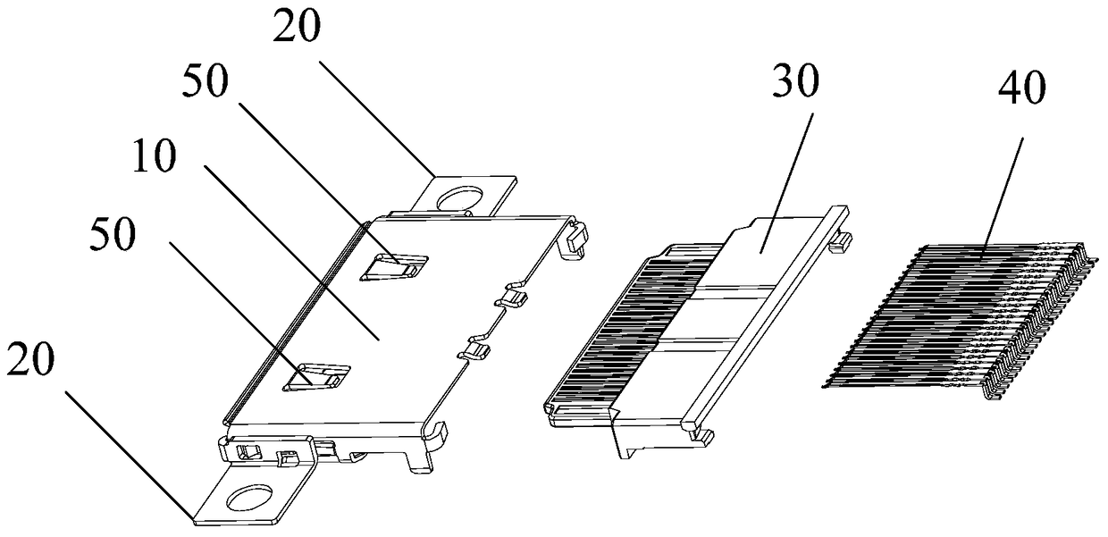
[0060] An embodiment of the present invention provides a connector, such as figure 1 Shown is a perspective view of the various components of the connector, which includes:
[0061] The shell 10 is used to protect the connector.
[0062] The side wings 20 connected with the housing 10 are arranged on the outer side of the housing 10, and the side wings 20 are used for fixing the connector on the electronic device.
[0063] An attachment 30 disposed inside the housing 10 and connected to the housing 10 , the attachment 30 is used to fix the pin 40 .
[0064] The pin 40 is disposed on the attachment 30 .
[0065] Wherein, the pins 40 at least include: power pins for transmitting power signals, USB pins for transmitting USB signals, network pins for transmitting network signals, and DP pins for transmitting DP signals.
[0066] It should be noted, figure 1 The number of pins in is only schematic and cannot be limited to the actual number of pins of the connector provided in t...
Embodiment 2
[0127] An embodiment of the present invention provides an electronic device, including the connector as described in the first embodiment.
[0128]Specifically, the female head of the connector provided by the embodiment of the present invention can be used on computers, notebook computers, tablet computers, large-sized mobile phones or docking stations, and correspondingly, the male head of the connector provided by the embodiment of the present invention can be used on Various external devices, such as drives, large-screen displays, keyboards, printers, scanners, etc.
[0129] Specifically, taking the electronic device as a docking station as an example, the electronic device provided with the connector as shown in the first embodiment will be described. The docking station is a base used to expand the functions of the notebook computer, and it can connect various external devices through interfaces and slots. It can make up for the shortcomings of thin and light notebooks ...
Embodiment 3
[0133] An embodiment of the present invention provides a method for using a connector, the schematic flow chart of which is as follows Figure 18 As shown, the embodiment of the present invention takes the electronic device as a computer, and the computer includes a connector female head, and the connector male head is USB as an example for illustration. The method of using the connector includes:
[0134] S101. The electronic device acquires a connector access signal.
[0135] Specifically, when the USB is plugged into the computer, the computer can obtain an access signal from the female connector on the computer.
[0136] S102. The electronic device detects the connector pin corresponding to the connector access signal and determines the type of the external device.
[0137] Specifically, after the computer obtains the access signal of the female connector, it detects that the access signal is a USB signal, so that it can determine that the external device is a USB device....
PUM
 Abstract
Description
Claims
Application Information
 - R&D
- Intellectual Property
- Life Sciences
- Materials
- Tech Scout
- Unparalleled Data Quality
- Higher Quality Content
- 60% Fewer Hallucinations
Browse by: Latest US Patents, China's latest patents, Technical Efficacy Thesaurus, Application Domain, Technology Topic, Popular Technical Reports.
© 2025 PatSnap. All rights reserved.Legal|Privacy policy|Modern Slavery Act Transparency Statement|Sitemap|About US| Contact US: help@patsnap.com