A brushless DC motor position detection circuit

A technology of brushed DC motor and detection circuit, which is applied in the direction of electronically commutated motor control, electrical components, control system, etc., can solve the problems that are difficult to be popularized and stray signals are difficult to control

Active Publication Date: 2018-07-06
CHERY AUTOMOBILE CO LTD
View PDF9 Cites 0 Cited by
  • Summary
  • Abstract
  • Description
  • Claims
  • Application Information

AI Technical Summary

Problems solved by technology

[0005] However, since the signal sampling circuit is directly taken out from the phase circuit, it is difficult to control various stray signals when the motor is running, especially when the motor is running at a low speed, the interference signal will even be greater than the useful signal to be collected, and it is difficult to be popularized in practical applications.

Method used


Image

  • A brushless DC motor position detection circuit
  • A brushless DC motor position detection circuit

Examples


Embodiment Construction

[0014] Below with reference to the accompanying drawings, through the description of the implementation examples, the specific embodiments of the present invention, such as the shape, structure, mutual position and connection relationship between each part, the role and working principle of each part, etc., will be further described. detailed instructions.

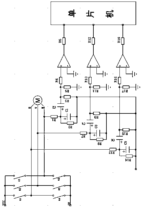
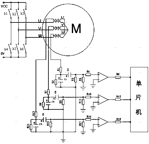
[0015] Such as figure 2 , the brushless DC motor position detection circuit of the present invention includes a brushless DC motor body, the brushless DC motor body includes a stator and a rotor, the stator is installed in the iron core slot by a multi-phase winding, the stator's The U, V, and W phase windings are all wound with the corresponding coupling coils U', V', W', and the coupling coils U', V', W' are star-connected. The detection circuit includes a DC power supply and a signal sampling circuit. The signal sampling circuit The input end is connected with coupling coils U', V', W'. Wherein, the DC power supply a...


PUM


Abstract

The invention provides a brushless direct current motor position detection circuit. The detection circuit can conveniently and accurately collect a brushless direct current motor rotor positioning signal. The detection circuit comprises a brushless direct current motor body; the brushless direct current motor body comprises a stator and a rotor; the stator is mounted in an iron core wiring duct through multiple phases of windings; the windings in each phase of the stator are coiled with corresponding coupling coils; the coupling coils are in star connection; the detection circuit comprises a direct current power supply and a signal sampling circuit; and the input end of the signal sampling circuit is connected with the coupling coils. The brushless direct current motor position detection circuit is based on a principle that the coupling coils output variable phase voltage due to induction; the induced voltage by the coupling coils is in direct proportion to the phase voltage amplitude of the brushless direct current motor, so that the induced voltage and the phase voltage amplitude are consistent in phase; the coupling coils are in star connection, so that the states of the connected coupling coils are equivalent to the states of the corresponding phases of the brushless direct current motor; and a star circuit formed by the coupling coils is fully isolated from a phase line of the brushless direct current motor, so that interferences generated in the operating of the brushless direct current motor are isolated.

Description

technical field [0001] The invention relates to the technical field of DC motors, in particular to a position detection circuit of a brushless DC motor. Background technique [0002] The control of the DC brushless motor is realized by switching the on-off state of the three-phase winding of the motor through the rotor position signal. Therefore, when controlling the brushless DC motor, it is necessary to detect the rotor position signal of the brushless DC motor to determine the switching time for switching the on-off state of the three-phase winding of the motor. [0003] CN1286525A Chinese invention patent application discloses an invention named "a rotor position detection method for a position sensorless brushless DC motor", which discloses a method such as figure 1 The shown position detection circuit has a detection circuit connected to the motor M. Wherein, the DC power supply Vcc is turned on and off in turn through the switching circuit, so that the U, V, and W t...

Claims


Application Information

Patent Timeline
Patent Type & Authority Patents(China)
IPC IPC(8): H02P6/185
CPCH02P6/185
Inventor 张绍山张绍勇
Owner CHERY AUTOMOBILE CO LTD
Why Eureka
Try Eureka