
Grass discharge and anti-blocking device for harvester and its working method
A harvester and grass-arranging technology, which is applied to harvesters, cutters, agricultural machinery and implements, etc., can solve problems such as hindering the development of inspection work, high labor intensity of cleaning work, affecting the normal work of machinery, etc., and achieves strong adaptability. , Improve the effect of weeding, easy disassembly
- Summary
- Abstract
- Description
- Claims
- Application Information
AI Technical Summary
Problems solved by technology
Method used
Image


Examples
Embodiment Construction
[0029] The present invention will be further described below in conjunction with accompanying drawing of description and specific embodiment:
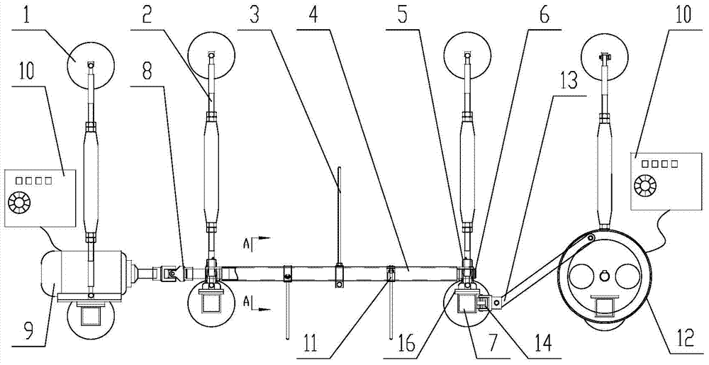
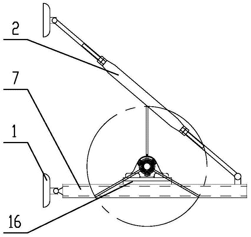
[0030] Such as figure 1 As shown, the harvester grass discharge and anti-blocking device includes a transmission tube shaft 4, and three shifting teeth 3 are installed on the transmission tube shaft 4, and the shifting teeth 3 are distributed in a spiral shape along the axial direction of the transmission tube shaft 4, as image 3 As shown, the three shifting teeth 3 circle around the transmission tube shaft 4, and the angle between them is 60°, forming a uniform distribution in the circumferential direction of the transmission tube shaft 4, while the transmission tube shaft 4 rotates on its axis The direction is reciprocating, and the transmission tube shaft 4 drives the shifting gear 3 to move, and the transmission tube shaft 4 is provided with a connecting device connected with the harvester.
[0031] The shifting tooth 3 is rod-sh...
PUM
 Abstract
Description
Claims
Application Information