kitchen grease trap

A technology for oil wells and kitchens, applied in the field of kitchen sewer purification devices, to achieve the effect of optimizing the structure and simplifying the operation

Active Publication Date: 2017-08-18
ZHUJI XINGUANG MUNICIPAL FACILITIES CO LTD
View PDF1 Cites 0 Cited by
  • Summary
  • Abstract
  • Description
  • Claims
  • Application Information

AI Technical Summary

Problems solved by technology

[0003] In view of the above structure, if you need to clean up the residue in the slag basket, you need to pull out the oil separator completely from the barrel, so that there will be liquid mixing between the clean water room and the sewage room, clean the oil separator and put it back When it is put into the barrel and continues to be used, there is no difference between the so-called clean water room and sewage water. After continuing to pass the sewage, the mixed sewage in the clean water room will inevitably be discharged into the sewer, so there is still room for improvement

Method used


Image

  • kitchen grease trap
  • kitchen grease trap
  • kitchen grease trap

Examples


Embodiment 1

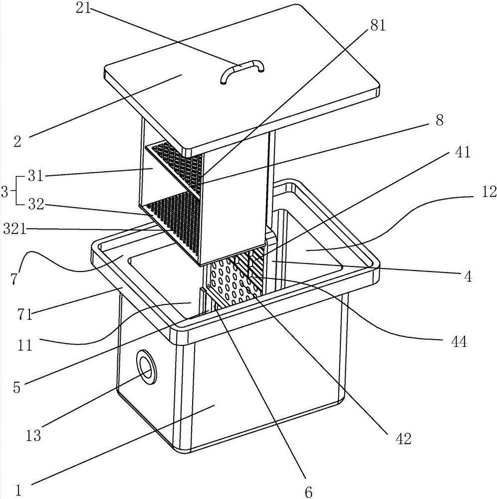
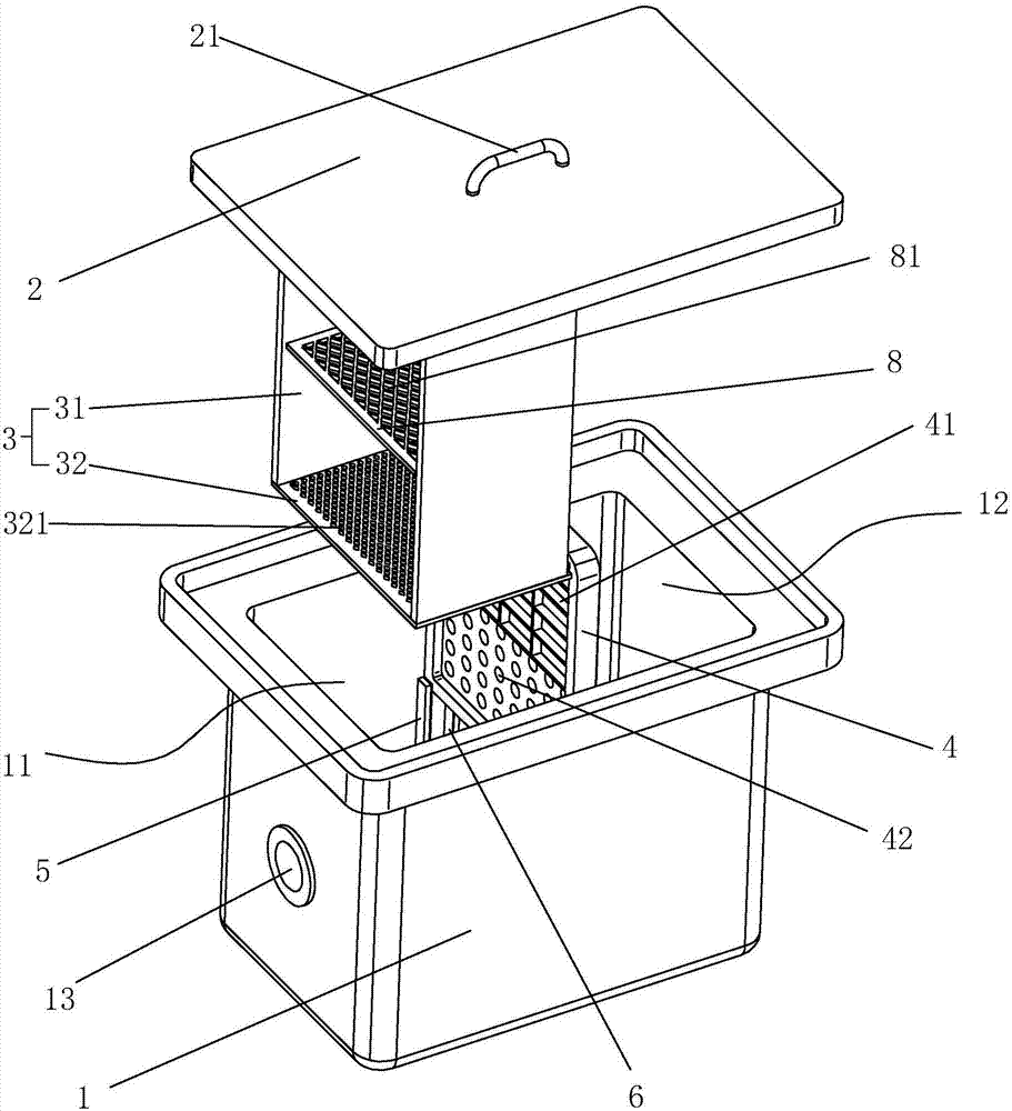
[0034] Embodiment one, combining figure 2As shown, the inner wall of the barrel body 1 is relatively provided with two chute 5, and the chute 5 is slidably connected with the oil separator 4, when the oil separator 4 is placed in the barrel body 1, the Barrel body 1 is divided into independent clean water room 12 and sewage room 11, and corresponding clean water room 12 and sewage room 11 are respectively provided with clean water outlet 14 and sewage inlet 13, and sewage inlet 13 is then connected to the water outlet of domestic sink, so The water purification outlet 14 described above is connected to the sewer inlet, and the chute 5 is provided with a gasket 6 on one side of the water purification room 12, the gasket 6 is made of rubber material, and the gasket 6 is arranged along the length direction of the chute 5 And fixedly connected with the chute 5, the length of the sealing pad 6 is roughly half of the chute 5, and one end of the sealing pad 6 is connected to the bot...

Embodiment 2

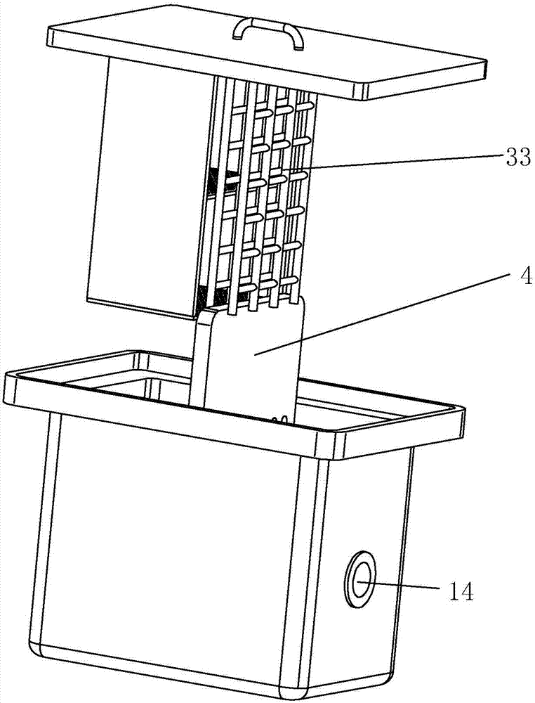
[0039] Embodiment two, such as Figure 3 to Figure 4 As shown, the oil separator 4 is provided with a number of positioning grooves 43 on one side of the clean water room 12, and the positioning grooves 43 are arranged along the depth direction of the barrel body 1, and all the positioning grooves 43 are gathered at the bottom of the oil separator 4. It is set at the middle position, the distance between the two positioning grooves 43 at the outermost edge is 1 / 2 of the total width of the oil separator 4, and the distance between two adjacent positioning grooves 43 is the same, and the reinforcing plate 33 is set It is a positioning strip one by one, and the positioning strip is matched with the positioning groove 43. The positioning strip is integrally connected to the connecting part 31. The connecting part 31 of this embodiment is two independent plates. Connected to the barrel cover 2, the other end is connected to both ends of the receiving plate 32. One end surface of th...


PUM


Abstract

The invention discloses a kitchen grease interceptor. The kitchen grease interceptor comprises a barrel body, a barrel cover and a grease separation plate which is provided with water filtration holes, wherein the grease separation plate is connected to the interior of the barrel body in a sliding manner, and divides the barrel body into a sewage chamber and a clear water chamber which are independent; a sewage inlet and a clear water outlet are formed in positions, corresponding to the sewage chamber and the clear water chamber, of the barrel body respectively; a receiving part for receiving residues is fixedly arranged on the barrel cover; when the barrel body is covered with the barrel cover, the receiving part is contacted with the bottom part of the barrel body on one side of the sewage chamber. The invention aims at providing a kitchen grease interceptor capable of preventing liquid in the sewage chamber and liquid in the clear water chamber from being mixed during residue removal, accordingly, the use manner of the kitchen grease interceptor is improved under the condition that original functions are guaranteed.

Description

technical field [0001] The invention relates to a kitchen sewer cleaning device, more specifically, it relates to a kitchen oil well. Background technique [0002] The kitchen oil trap is mainly used to add a filtering process before the kitchen sewage is passed into the sewer. The kitchen sewage is usually a mixture of water and oil, and the kitchen sewage will also be mixed with some kitchen waste such as vegetable leaves. The patent number is CN205046665U. A kitchen oil separation well, the kitchen oil separation well includes a barrel body, an oil separator and a slag basket, the oil separator can be withdrawn and vertically installed in the barrel body and divides the inner space of the barrel body into one side It is a sewage room and the other side is a water purification room. The barrel body has a sewage inlet on the barrel wall on one side of the sewage room, and a clean water opening on the barrel wall on the side of the water purification room. Outlet, the slag ...

Claims


Application Information

Patent Timeline
Patent Type & Authority Patents(China)
IPC IPC(8): E03C1/264
CPCE03C1/264
Inventor 徐钢
Owner ZHUJI XINGUANG MUNICIPAL FACILITIES CO LTD
Why Eureka
Try Eureka