Mitral balloon closing plate obstruction body implanted via tip of heart and implantation method

一种闭合板、经心尖的技术,应用在心脏瓣膜、假体、医药科学等方向,能够解决降低心脏效率、可靠性不高、人体创伤大等问题,达到残余反流发生率低、可靠性强、创伤小的效果

Active Publication Date: 2016-07-06
JIANGSU UNIV
View PDF6 Cites 9 Cited by
  • Summary
  • Abstract
  • Description
  • Claims
  • Application Information

AI Technical Summary

Problems solved by technology

When the mitral valve 2 is closed, the state is as follows Figure 5 , Image 6 When shown, there is a gap between the front and rear leaflet junctions 5 of the mitral valve 2, and the gap between the front and rear leaflet junctions makes blood flow back from the left ventricle 3 to the left atrium 1 during systole (as shown in FIG. Figure 5 The direction of the regurgitation shown by the arrow in ), this backflow is called mitral regurgitation, and mitral regurgitation reduces the efficiency of the heart and leads to heart failure
[0005] At present, the treatment methods for mitral valve regurgitation mainly include annuloplasty, mechanical mitral valve or biological mitral valve transplantation, etc., most of which require open chest and open heart, which cause great trauma to the human body and are not reliable. , leading to relapse of mitral regurgitation in 50% of cases within 5 years of treatment
The existing relatively advanced minimally invasive treatment method is to clamp the midpoints of the front and rear leaflet edges together by clamping the mitral valve to form two independent blood flow channels to reduce blood regurgitation, but this method has Residual reflux occurs

Method used


Image

  • Mitral balloon closing plate obstruction body implanted via tip of heart and implantation method
  • Mitral balloon closing plate obstruction body implanted via tip of heart and implantation method
  • Mitral balloon closing plate obstruction body implanted via tip of heart and implantation method

Examples


Embodiment Construction

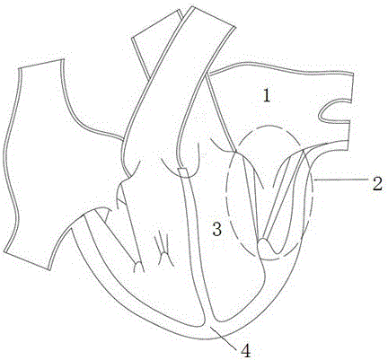
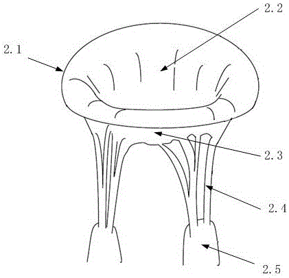
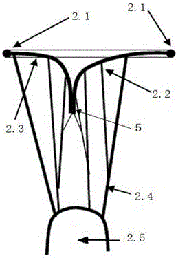
[0027] see Figure 7 According to the present invention, the structure of a mitral valve closure plate obstructing body implanted through the apex of the heart includes a hook card 6 , a balloon closure plate 7 , a guide wire 8 , a guide ring 13 and a fixing plug 12 . A fixed plug 12 is implanted at the apex 4 of the heart. There are two hooks 6, respectively implanted in the left and right positions of the mitral annulus 2.1 at the anterior and posterior leaflet junction 5. The inside of the airbag closing plate 7 is an airbag, and the inside of the airbag is filled with gas or a curable liquid. The curable liquid is a liquid when filled, and can become solid after a certain period of time or injection of a curing agent after being filled into the airbag. substance. The shape of the longitudinal section of the airbag closing plate 7 is an inverted isosceles trapezoidal structure, and the length of the upper base of the isosceles trapezoid is longer than the length of the lo...


PUM


Abstract

The invention discloses a mitral balloon closing plate obstruction body implanted via the tip of the heart in the technical field of systemic heart repair and an implantation method. A balloon closing plate is made from an elastic plastic material capable of being filled with gas or solidifiable liquid, is implanted through a small incision of a left chest of a human body, enters a left ventricle via the tip of the heart, and is put and fixed to a regurgitation hole in the closing part of the front and back valve leaflets of a mitral valve; during diastole, the mitral valve is opened, and blood flows into the left ventricle from a left atrium through two channels between the front valve leaflet and the balloon closing plate and between the back valve leaflet and the balloon closing plate; during systole, the front and back valve leaflets are closed, and the edges of the valve leaflets closely fit the balloon closing plate, so that a regurgitation channel of the mitral valve is obstructed and the regurgitation of the mitral valve is effectively prevented; and the balloon closing plate obstruction body is simple in structure and high in reliability, the wound on the human body is small in the implantation method for the balloon closing plate obstruction body, the occurrence rate of residual regurgitation is very low, the diseases such as functional mitral regurgitation and the like can be treated, and the success rate of functional mitral regurgitation repair reaches more than 90%.

Description

technical field [0001] The invention relates to the field of human heart repair technology and medical devices, in particular to a device capable of repairing heart mitral valve regurgitation. Background technique [0002] Human heart and valves such as figure 1 As shown, the left ventricle 3 is located at the upper left of the apex 4, and the mitral valve 2 is located between the left atrium 1 and the left ventricle 3, and the mitral valve 2 controls the unidirectional flow of blood from the left atrium 1 into the left ventricle 3. A dysfunctional mitral valve 2 causes both leaflets of the mitral valve 2 to regurgitate, allowing blood to flow back from the left ventricle 3 back into the left atrium 1 during systole. Mitral regurgitation will cause pulmonary congestion and hypertrophy of the left ventricle3, eventually leading to heart failure and death of the patient. [0003] The structure of mitral valve 2 is as follows figure 2 As shown, the mitral valve 2 is a compl...

Claims


Application Information

Patent Timeline
Patent Type & Authority Applications(China)
IPC IPC(8): A61B17/00
CPCA61B17/0057A61B2017/00592A61B2017/00579A61B2017/00623A61F2/246A61F2220/0016A61B17/0401A61B2017/0464A61F2210/0085A61F2250/0003A61F2/2454A61F2/2466
Inventor 贺照明荆腾张凯亮
Owner JIANGSU UNIV
Why Eureka
Try Eureka