Special-shaped metal cantilever weighing device

A cantilever beam and metal sheet technology, applied in the field of weight sensors, can solve the problems of large size, large scale thickness, sensor installation, etc., and achieve the effect of high output sensitivity

Inactive Publication Date: 2016-07-27
PICOOC TECH CO LTD
View PDF15 Cites 4 Cited by
  • Summary
  • Abstract
  • Description
  • Claims
  • Application Information

AI Technical Summary

Problems solved by technology

Sensors of this height cannot meet the small height requirements of the support feet of ultra-thin human scales
[0005] Second, since the weighing sensor is a transformation element that converts the micro-deformation generated by the torque into a corresponding electrical signal, the existing sensors used for platform scales are usually a cantilever beam structure with upper and lower parallel holes, and its disadvantages are high processing costs and large volume , especially the defect of large height and size of the elastic body, so it cannot meet people's requirements for light, small and beautiful platform scales today
[0009] a. The measuring range is too large, the accuracy is poor, and the output sensitivity is poor;
[0010] b. The size and volume are too large, resulting in the thickness of the scale being too large or the sensor cannot be installed at the four corners of the scale body, that is, the width of the sensor is large, resulting in a large distance between the force point of the sensor and the edge of the scale body. At the same time, considering the thickness of the sensor Larger scales lead to thicker scales, which eventually lead to easy rollover of the scales, threatening the personal safety of users;
[0011] c. The traditional cantilever beam sensor is easy to twist its root or rear due to the bending of the cantilever beam in the horizontal direction, resulting in distortion, which in turn leads to low measurement accuracy

Method used


Image

  • Special-shaped metal cantilever weighing device
  • Special-shaped metal cantilever weighing device
  • Special-shaped metal cantilever weighing device

Examples


Embodiment Construction

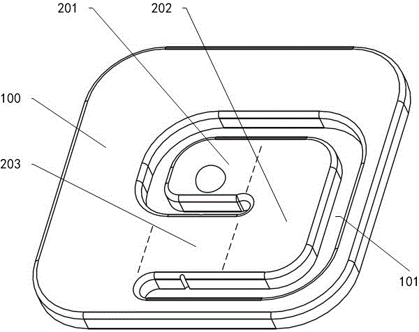
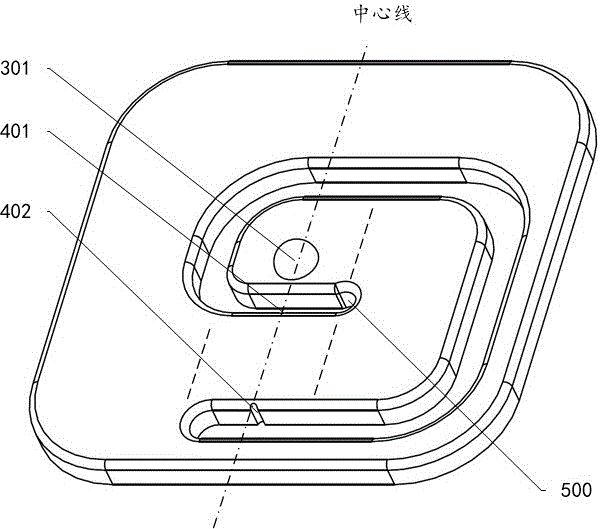
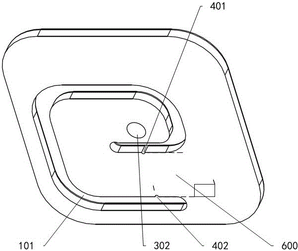
[0039] likefigure 1 As shown, the present invention provides a weight sensor for a scale, which is simple in structure, easy to install and manufacture, and improves the measurement performance of the scale. Formed, the metal sheet 100 and the hollow part 101 together form a cantilever beam shaped like a letter C, the hollow part 101 and the middle part of the metal sheet 100 form the cantilever beam front part 201, and the part perpendicular to the cantilever beam front part 203 is the middle part 202 of the cantilever, the rest of the cantilever is the rear part 203 of the cantilever, and the front part 201 of the cantilever is the free end, which has a front protrusion 301 and a corresponding front recess 302 .

[0040] Specifically, the width of the cantilever front part 201 is 10% wider than that of the cantilever rear part 203, so that the front protrusion 301 and the corresponding front depression 302 are formed at the same time as the cantilever front part (203) , with...


PUM

PropertyMeasurementUnit
thicknessaaaaaaaaaa
lengthaaaaaaaaaa
thicknessaaaaaaaaaa

Abstract

The invention provides a special-shaped metal cantilever weighing device.A flaky weight sensor is formed by a rectangular metal sheet (100) with a G-shaped hollowed-out part (101).The metal sheet (100) and the hollowed-out part (101) jointly form a C-shaped cantilever.The part between the hollowed-out part (101) and the metal sheet forms a cantilever front part (201), the part perpendicular to the cantilever front part (201) is a cantilever middle part (202), and the remaining part of the cantilever is a cantilever rear part (203).The cantilever front part (201) is a free end provided with a front protrusion (301) and a corresponding front pit (302).The special-shaped metal cantilever weighing device is characterized in that the width of the cantilever front part (201) is 10% larger than that of the cantilever rear part (203) so that overlarge torque cannot be generated on the cantilever rear part (203) while the front protrusion (301) and the corresponding front pit (302) are formed on the cantilever front part (201).

Description

technical field [0001] The present invention relates to a sensor for measuring force, in particular, to a weight sensor with a sheet metal cantilever beam structure. Background technique [0002] The scales in the prior art include a scale for weighing a human body, which has a surface for receiving a weight to be weighed, a base for placing on a plane and a sensor carrying a strain gauge. Such scales are described, for example, in European Patent Nos. 141710 and 317429. [0003] In this prior art scale, only one sensor in the form of a metal cantilever is placed between the plate and the base. Since the weight to be weighed acts on the platform, the above-mentioned metal cantilever beam basically bears the bending moment, but also bears unnecessary moment, especially torque, because the point of action of the weight to be weighed may be offset from the sensor. The strain gauge is connected to an electronic circuit so as to convert the deformation of the strain gauge into ...

Claims


Application Information

Patent Timeline
Patent Type & Authority Applications(China)
IPC IPC(8): G01G19/44G01G3/13G01G21/00
CPCG01G19/44G01G3/13G01G21/00
Inventor 蒙元鹏王绍云
Owner PICOOC TECH CO LTD
Why Eureka
Try Eureka