Heating stove based on honeycomb ceramic heat accumulators

A technology of honeycomb ceramics and regenerators, which is applied to furnaces/stoves with hot water devices, household heating, heating methods, etc., which can solve problems such as insufficient fuel combustion and large smoke and dust emissions, and achieve combustion Sufficient, less NOx generation, good combustion stability

Active Publication Date: 2016-08-03
SHIJIAZHUANG JINTONG MACHINERY CO LTD
View PDF7 Cites 2 Cited by
  • Summary
  • Abstract
  • Description
  • Claims
  • Application Information

AI Technical Summary

Problems solved by technology

Although the heat exchange of this civilian coal-fired heating furnace is sufficient,

Method used


Image

  • Heating stove based on honeycomb ceramic heat accumulators
  • Heating stove based on honeycomb ceramic heat accumulators
  • Heating stove based on honeycomb ceramic heat accumulators

Examples


Embodiment 1

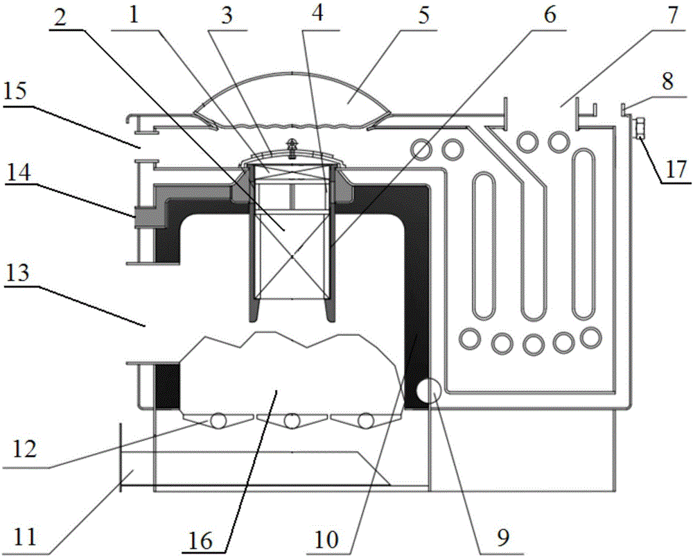
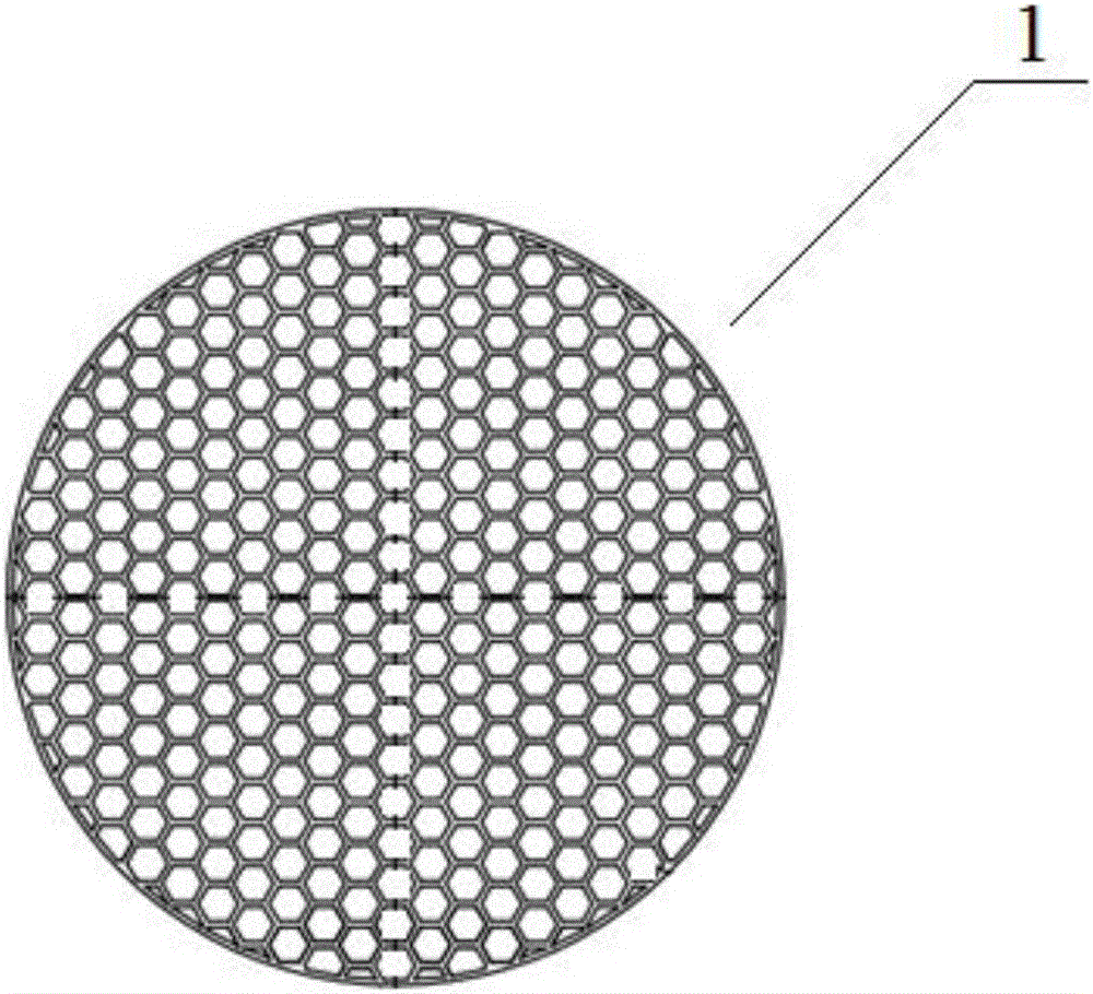
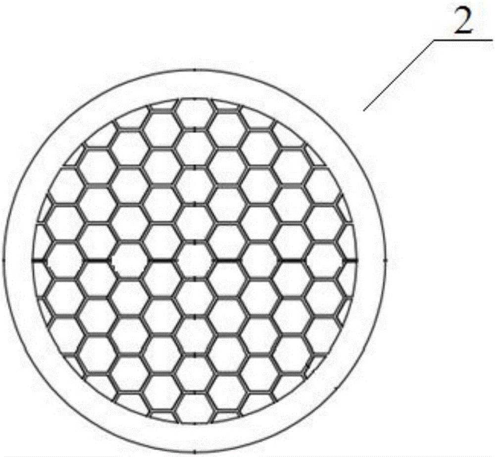
[0036] Such as Figure 1-Figure 3 As shown, a heating furnace based on a honeycomb ceramic regenerator includes a furnace body, a furnace chamber is provided inside the furnace body, a fire outlet is provided at the upper end of the furnace chamber, and a sheath is embedded in the fire outlet The sleeve 6, the sheath sleeve 6 is a cylindrical shape with upper and lower openings, and the first honeycomb ceramic regenerator 1 and the second honeycomb ceramic regenerator 2 are embedded in the sheath sleeve 6, and the first honeycomb ceramic regenerator The regenerator 1 is located above the second honeycomb ceramic regenerator 2, and the first honeycomb ceramic regenerator 1 and the second honeycomb ceramic regenerator 2 are separated by a support body 4 to form a secondary combustion chamber. Both the first honeycomb ceramic regenerator 1 and the second honeycomb ceramic regenerator 2 have several vertically arranged through holes, and the cross-sectional area of ​​the through h...

Embodiment 2

[0049] In this embodiment, the hole patterns of the through holes of the first honeycomb ceramic heat storage body 1 and the hole shape of the first honeycomb ceramic heat storage body 2 are both regular quadrilaterals.

[0050] Such as Figure 4 As shown, the heating cover 5 is a container-type circular arched heating cover, the middle of the top of the heating cover 5 is connected through a pipe to the side of the heating water supply pipe, and the side of the heating cover 5 is passed through another One pipe is connected through to the side of the heating return pipe; one end of the heating water supply pipe is connected to the water outlet 8 of the circulating water tank in the furnace body, and the other end is connected to the water inlet end of the radiator; one end of the heating return pipe is connected to the furnace body The water tank return port 9 of the circulating water tank, the other end is connected to the return water end of the radiator; the heating cover ...


PUM


Abstract

The invention belongs to the technical field of heating stoves and relates to a heating stove based on honeycomb ceramic heat accumulators. The heating stove based on the honeycomb ceramic heat accumulators comprises a stove body. A stove chamber is formed in the stove body. A flame outlet is formed in the upper end of the stove chamber. A protective sleeve is arranged in the flame outlet in an embedded mode. The first honeycomb ceramic heat accumulator and the second honeycomb ceramic heat accumulator are arranged in the protective sleeve in an embedded mode. The first honeycomb ceramic heat accumulator is located above the second honeycomb ceramic heat accumulator. The first honeycomb ceramic heat accumulator and the second honeycomb ceramic heat accumulator are separated through a supporting body, and a secondary combustion chamber is formed. The first honeycomb ceramic heat accumulator and the second honeycomb ceramic heat accumulator are each provided with a plurality of through holes formed in the vertical direction. The cross section area of each through hole of the first honeycomb ceramic heat accumulator is smaller than that of each through hole of the second honeycomb ceramic heat accumulator. Fire bars used for supporting fuel are arranged at the bottom of the stove chamber. The lower end of the protective sleeve is suspended above the fuel. A fuel feeding and first air distribution port, a second air distribution port and a third air distribution port are formed in the stove body. By the adoption of the heating stove based on the honeycomb ceramic heat accumulators, the fuel utilization rate is increased, the pollutant discharge amount is decreased, energy is saved, and environmental friendliness is achieved.

Description

technical field [0001] The invention belongs to the technical field of heating furnaces, and relates to a civil heating furnace, in particular to a heating furnace based on a honeycomb ceramic regenerator. Background technique [0002] Most of the existing civil heating furnaces, especially coal-fired civil heating furnaces, adopt direct-fired or reverse-fired types. Whether it is direct-fired or reverse-fired, the possibility of complete combustion is very small, and the emission of smoke and dust is very low. The amount is large, the combustion is insufficient, and the heat loss is large. [0003] For example, Chinese patent 201420500702.1 discloses a coal-fired heating stove for civilian use. Including the furnace body shell and the top cover, the lower part of the sealed chamber formed by the furnace body shell is the furnace, the furnace is equipped with a grate, the middle part of the top cover is provided with a coal filling port, and there are at least two layers of...

Claims


Application Information

Patent Timeline
IPC IPC(8): F24B1/183F24B1/191F24B1/197
CPCF24B1/183F24B1/191F24B1/1915F24B1/197
Inventor 周新山周舒怡
Owner SHIJIAZHUANG JINTONG MACHINERY CO LTD
Why Eureka
Try Eureka