a combined combustion chamber

A combustion chamber and pre-combustion stage technology, which is applied in the field of combustion chamber to achieve high-efficiency and low-emission combustion, widen the flame stability range, and strengthen the effect of blending

Active Publication Date: 2018-06-01
NANJING UNIV OF AERONAUTICS & ASTRONAUTICS
View PDF8 Cites 0 Cited by
  • Summary
  • Abstract
  • Description
  • Claims
  • Application Information

AI Technical Summary

Problems solved by technology

[0002] With the further development of aero-engine technology, the thrust-to-weight ratio continues to increase, the inlet temperature of the combustion chamber increases, the oil-gas ratio and temperature rise of the combustion chamber increase, and the requirements for the performance of the combustion chamber gradually increase, but at the same time, the weight of the combustion chamber is limited. However, it is increasing further. Therefore, the development of high oil-gas ratio combustors is facing many technical challenges: 1. Work stably in a wider range, mainly to solve the combustion stability under low power status and visible exhaust gas under high power status. Smoky combustion; 2. Under the conditions of reduced cooling gas distribution and cooling gas quality, further maintain or even improve the durability of the flame tube; 3. Reduce pollutant emissions in a large state; 4. Turbine under extremely high temperature conditions To work normally in the environment, the outlet temperature distribution coefficient of the combustion chamber must be greatly reduced

Method used


Image

  • a combined combustion chamber
  • a combined combustion chamber
  • a combined combustion chamber

Examples


Embodiment Construction

[0033] The present invention will be described in detail below with reference to the drawings and specific implementations.

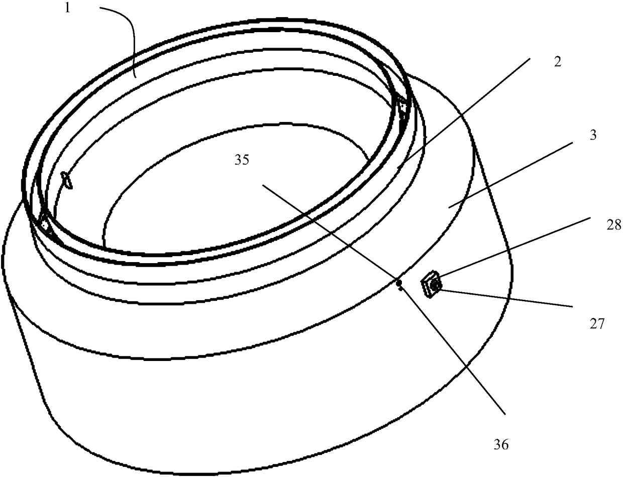
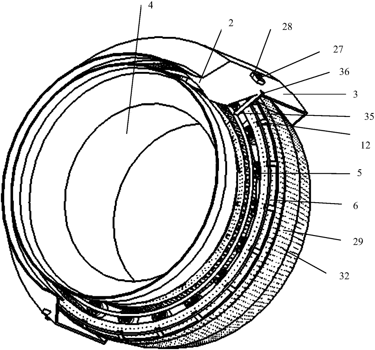
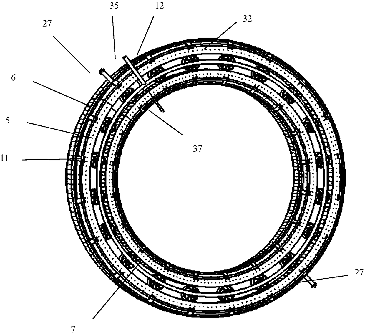
[0034] Please refer to Figure 1 to Figure 5 As shown, the combined combustion chamber of the present invention is mainly composed of a diffuser 2, a combustion outdoor casing 3 and an inner casing 4, a flame tube 29 with a double cavity structure on the head, a high-energy ignition nozzle 27, a swirler 11, etc. composition. The combined combustion chamber has a full annular structure, and the pre-combustion stage outer cavity 16 and the pre-combustion stage inner cavity 17 formed by a special structural design are used to form the pre-combustion stage outer cavity recirculation zone 22 and the pre-combustion stage inner cavity The recirculation zone 23 stabilizes the flame, and the flame is transmitted from the outer cavity 16 to the inner cavity 17 and the main flow by relying on the cross-fire plate 26 formed by the flame tube between the two cavities....


PUM


Abstract

The invention relates to a combination combustion chamber. A combustion chamber head part consists of a main combustion stage and a pre-combustion stage; the main combustion stage consists of a single-grade axial cyclone, a main combustion stage nozzle and a venturi pipe; and the pre-combustion stage consists of double concave cavities and a pre-combustion stage nozzle. The main combustion stage adopts a single-oil-way centrifugal nozzle, and enables fuel to reach needed concentration and particle size distribution through pressure atomization. The pre-combustion stage adopts an evaporation pipe type nozzle; and the fuel is sprayed to an evaporation pipe for primary atomization through a straight spraying nozzle, and performs secondary atomization and evaporation mixing in the evaporation pipe under an air shearing effect. The combination combustion chamber not only can achieve the purpose of reducing the pollutant discharge in a low-pollution combustion chamber, but also can solve the problems of small-state combustion instability and large-stage visible smoke in a high-temperature-rise combustion chamber so as to widen stable working range of the high-temperature-rise combustion chamber through classified combustion, in particular special structural design and arrangement mode of the pre-combustion stage and the main combustion stage.

Description

Technical field [0001] The invention relates to a combined combustion chamber, which is mainly used as a combustion chamber in aero engines, ground and marine gas turbines. Background technique [0002] With the further development of aero-engine technology, the thrust-to-weight ratio continues to increase, the inlet temperature of the combustion chamber increases, the fuel-air ratio and temperature rise of the combustion chamber increase, and the requirements for the performance of the combustion chamber gradually increase, but at the same time the weight of the combustion chamber is restricted However, it is increasing further. Therefore, the development of high-fuel-gas ratio combustion chambers faces many technical challenges: 1. Stable operation in a wider range, mainly to solve the combustion stability under low power conditions and the visible exhaust gas under high power conditions Smoke and combustion; 2. Under the conditions of reduced cooling gas distribution and reduc...

Claims


Application Information

Patent Timeline
Patent Type & Authority Patents(China)
IPC IPC(8): F23R3/04F23R3/28F23R3/32F23R3/34F23R3/36F23R3/52
CPCF23R3/04F23R3/286F23R3/32F23R3/34F23R3/36F23R3/52
Inventor 何小民李明玉赵玉玲葛正好黄卫东江平朱一骁黄亚坤
Owner NANJING UNIV OF AERONAUTICS & ASTRONAUTICS
Why Eureka
Try Eureka