Anti-skid drilling tool for stick-slip reduction with multi-start screw

A drilling tool and helical transmission technology, which is applied to drilling equipment, drill pipes, drill pipes, etc., can solve problems such as the influence of drilling tool performance and the inconvenience of drilling operations, and achieve high-efficiency rock breaking, fast rotation speed, and high transmission efficiency Effect

CN106050160BActive Publication Date: 2018-06-22沛县东宝机电设备有限公司
8 Cites 0 Cited by

Patent Information

Authority / Receiving Office
CN · China
Patent Type
Patents(China)
Current Assignee / Owner
Publication Date
2018-06-22

Smart Images

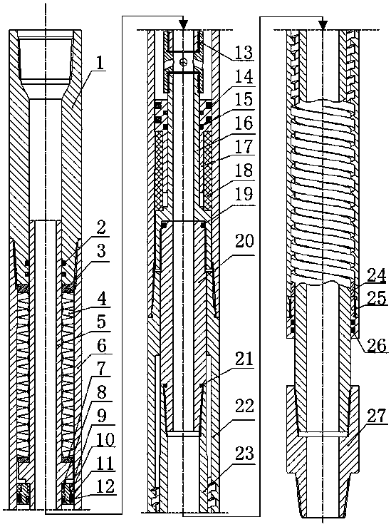
  • Figure 1
    Figure 1
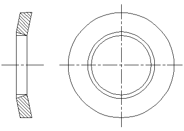
  • Figure 2
    Figure 2
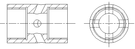
  • Figure 3
    Figure 3
Patent Text Reader

Abstract

The invention relates to a stagnation-prevention drilling tool capable of reducing a stick slip phenomenon through a multi-head helical pair. The stagnation-prevention drilling tool is installed on the upper portion of a drill bit in a thread connection mode and comprises an upper assembly, a vibration absorption assembly and a lower assembly. The rear end of the vibration absorption assembly is provided with an upper connector assembly, and the front end of the vibration absorption assembly is provided with the lower assembly. Vibration generated in the work process of the tool is absorbed through disc springs connected in series, a pressure cavity and a rubber spring. Through matching of a spiral outer shell and a spiral transmission shaft, the multi-head helical pair is formed. When the reaction torque acting on the drill bit is increased and a stick slip or clamping phenomenon occurs, the spiral transmission shaft rotates backwards relative to the spiral outer shell, and therefore small-amplitude reverse rotation is applied to the drill bit. The reaction force of the ground to the drill bit is lowered, stress of the drill bit reaches balance again, and therefore efficient rock breaking with the drill bit is realized. According to the stagnation-prevention drilling tool capable of reducing the stick slip phenomenon through the multi-head helical pair, the vibration generated during rock breaking with the drill bit can be absorbed, the stick slip phenomenon is reduced, and continuous drilling of the drill bit is guaranteed.
Need to check novelty before this filing date? Find Prior Art

Description

technical field

[0001] The invention belongs to the field of petroleum and natural gas drilling engineering and relates to a novel downhole drilling tool, in particular to an anti-stagnation drilling tool capable of reducing stick-slip through a multi-head screw. Background technique

[0002] At present, oil and gas exploration and development have entered a bottleneck state. The development of conventional oil and gas fields has gradually entered the later stage. Global oil and gas development has gradually shifted to unconventional oil and gas development, gradually shifting from shallow to deep and ultra-deep layers, and from land to ocean development. With the changes in the mining environment of oil and gas fields, the requirements for their mining modes and technologies are getting higher and higher. Compared with the development of conventional oil and gas fields, the difficulty of oil and gas extraction in deep, ultra-deep oil and gas and complex geological structures...

Examples

Embodiment Construction

[0015] The present invention will be further described below in conjunction with accompanying drawing:

[0016] see figure 1 , the anti-sluggish drilling tool that utilizes the multi-head screw to achieve viscosity-slip reduction is composed of an upper joint assembly, a vibration-absorbing assembly and a lower assembly. The upper joint assembly is installed at the rear end of the vibration-absorbing assembly, and the lower assembly is installed at the front end. The upper joint assembly includes an upper joint 1, a disc spring 4, a central pipe 5, a rectangular sealing ring a2, an upper joint gasket 3, and a gasket 7. The rectangular sealing ring a2 is installed on the inner circumference of the front end of the upper joint 1, and the The gasket 7 is installed on the central tube 5, the front end of the disc spring 4 is in contact with the gasket 7, the rear end is in contact with the upper joint gasket 3, and finally the upper joint gasket 3 is installed on the central tube ...