Oil pumping unit indicator diagram learning estimating method

A technology of pumping unit and dynamometer, applied in the field of data mining, can solve the problems of high cost, limited prospects and significance, theft, etc., and achieve the requirements of relaxing measurement accuracy, strong application prospects and value, and compensating for measurement errors Effect

Active Publication Date: 2016-11-02
INST OF SEMICONDUCTORS - CHINESE ACAD OF SCI
View PDF5 Cites 2 Cited by
  • Summary
  • Abstract
  • Description
  • Claims
  • Application Information

AI Technical Summary

Problems solved by technology

[0004] However, it is not an effective method to directly use the load cell to measure the load. This technology has the following defects: On the one hand, since the load cell has been in the process of stretching under alternating loads, it needs to withstand a huge tensile force for a long time , its elastic coefficient is easy to change, which affects the measurement accuracy of the sensor and accelerates the failure, resulting in a short service life of the sensor and making it difficult to achieve long-term effective monitoring; on the other hand, the sensor needs to be installed on the frame and polished rod of the pumping unit It is connected to the main control instrument through a long-distance lead wire, which is complicated and inconvenient to disassemble and install. The maintenance workload is heavy, the cost is high, and it is prone to man-made damage and theft, resulting in a decrease in system stability and reliability.
[0007] Second, some steps are computationally complex
On the one hand, it leads to a large space-time overhead, and on the other hand, it is also prone to singularities
[0008] Third, the accuracy of the results needs to be improved
The dynamometer diagram obtained by indirect calculation does not coincide well with the actual measured value, which limits the prospect and significance of its practical application

Method used


Image

  • Oil pumping unit indicator diagram learning estimating method
  • Oil pumping unit indicator diagram learning estimating method
  • Oil pumping unit indicator diagram learning estimating method

Examples


Embodiment

[0069] In order to verify the effect of the learning estimation method of a kind of pumping unit dynamometer diagram of the present invention, carry out following experiment:

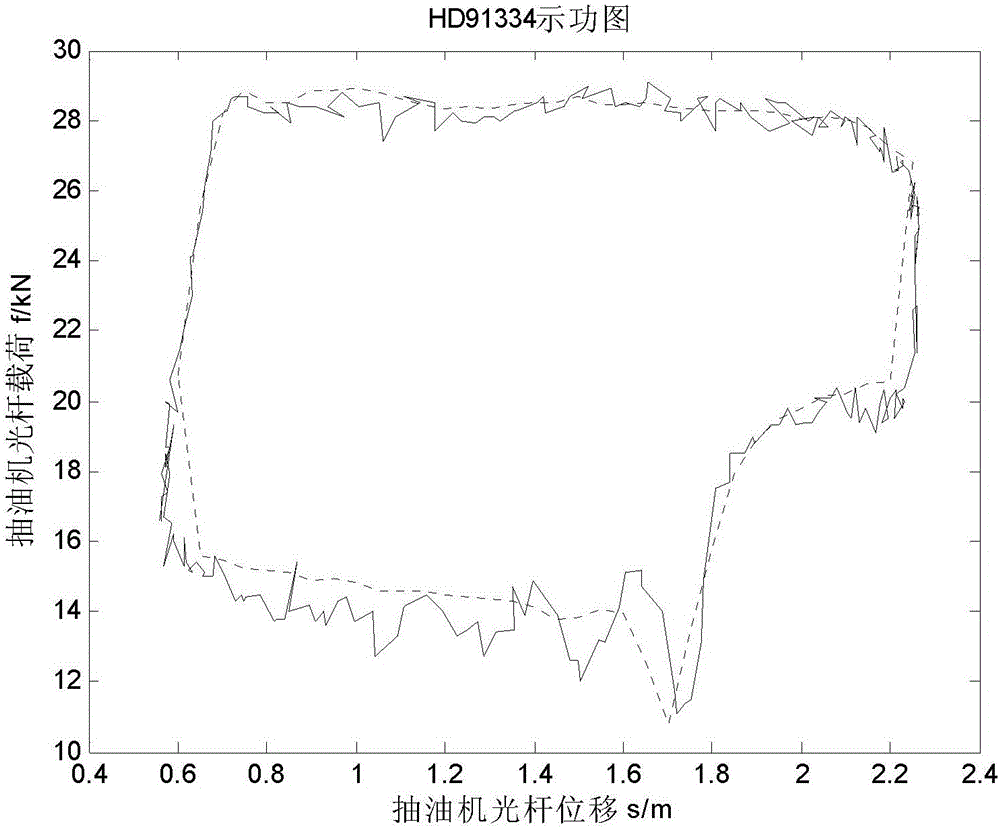
[0070] The measured data of the pumping units of 4 oil wells numbered HD91334, HD91353, HD91354 and HD91409 were randomly selected for experiments to form 4 sets of experimental sample data, in which the first 50 data records were selected as the learning data for each set of sample data, and the 100th data records as test data.

[0071] The experimental results are shown in Figure 3, where the dotted line represents the estimated curve and the solid line represents the measured curve. It can be seen from the figure that although the dynamometer curves corresponding to the four groups of experiments have different shapes, the estimated curves can fit the measured curves well.

[0072] The software platform for the 4 groups of experiments is Matlab-R2013a, and the hardware platform is a PC with 2.66GHz ...


PUM


Abstract

The invention discloses an oil pumping unit indicator diagram learning estimating method comprising the following steps: S1, pre-processing original data records, so the data records can be complete and usable; S2, space-regularizing pre-processed data records, so each data record can be mapped to an uniform displacement sequence, wherein the displacement refers to the oil pumping unit displacement; S3, using regularized data records to compute the characteristic coefficient alpha (s), wherein the characteristic coefficient represents an influence factor on the motor power changes by oil pumping unit load changes, s represents oil pumping unit polished rod displacement; S4, using the learned characteristic coefficient alpha (s) to estimate to-be-estimated oil pumping unit indicator diagram data. The oil pumping unit indicator diagram learning estimating method is less in learning parameters, small in processing space-time cost, and high in robustness and accuracy.

Description

technical field [0001] The invention relates to the field of data mining, in particular to a method for learning and estimating an indicator diagram of a pumping unit. Background technique [0002] During the work and management of the oil well, the staff need to keep abreast of the dynamic parameters of the pumping unit, and analyze various information such as the working condition of the pumping unit and the state of downhole oil. These measures are crucial to confirm whether the oil well is working normally and to troubleshoot and resolve abnormal conditions, and are necessary means to ensure oil pumping efficiency and maintain oil well safety. [0003] The dynamometer diagram of the pumping unit is the relationship curve between the load and displacement of the polished rod of the pumping unit. It has become an important and main method of oil well condition diagnosis. Therefore, in actual work, we need to obtain the dynamometer diagram of the pumping unit in real time...

Claims


Application Information

Patent Timeline
Patent Type & Authority Applications(China)
IPC IPC(8): G06F15/18
CPCG06N20/00
Inventor 方睿鲁华祥来疆亮边昳
Owner INST OF SEMICONDUCTORS - CHINESE ACAD OF SCI
Why Eureka
Try Eureka