High-frequency CRM boost type PFC converter capable of adaptively optimizing THD (total harmonic distortion)

A converter and self-adaptive technology, applied in high-efficiency power electronic conversion, output power conversion device, conversion of AC power input to DC power output, etc. Meeting the application requirements of high-frequency CRMBoostPFC converters

Active Publication Date: 2016-11-09
NANJING UNIV OF AERONAUTICS & ASTRONAUTICS
View PDF7 Cites 18 Cited by
  • Summary
  • Abstract
  • Description
  • Claims
  • Application Information

AI Technical Summary

Problems solved by technology

[0008] 1. The additional conduction time only changes synchronously with the instantaneous value of the input voltage, and has no relationship with the output power, so it cannot achieve the optimal change of conduction time control, and it can improve the input current THD performance under different output powers The effects are very different and even cannot be taken into account;
[0009] 2. The acquisition of the additional on-time lacks accurate quantitative calculation, and can only achieve better input current THD performance under a certain input voltage and a certain output power within the working condition range of the converter. Therefore, the components of the control circuit The parameters need to be compromised after comparing and testing the input current THD performance under different working conditions (different input voltage and different output power) within the working condition range, which increases the design cycle and complexity;
[0010] 3. The actual required change of on-time is closely related to the switching frequency of the converter. The additional on-time that can be increased by existing commercial analog control chips is only suitable for a limited range of switching frequencies, most of which are between 30kHz and 200kHz. Meet the application needs of higher switching frequency
[0012] 1. The cost and power consumption of the digital controller will increase significantly;
[0013] 2. There is an upper limit in the calculation speed of the existing digital controller, so the calculation speed and control accuracy of the conduction time cannot be considered at the same time;
[0014] 3. Existing digital controllers have limited ability to detect high-frequency periodic signals
[0018] 2. The output current of the converter needs to be sampled to calculate the output power, which increases the system cost and implementation complexity
[0019] Therefore, the digital method based on the look-up table is difficult to meet the application requirements of high-frequency CRM Boost PFC converters in wide input voltage and wide load applications

Method used


Image

  • High-frequency CRM boost type PFC converter capable of adaptively optimizing THD (total harmonic distortion)
  • High-frequency CRM boost type PFC converter capable of adaptively optimizing THD (total harmonic distortion)
  • High-frequency CRM boost type PFC converter capable of adaptively optimizing THD (total harmonic distortion)

Examples


Embodiment 1

[0081] Embodiment 1: The generation method of the changing conduction time curve (used in the look-up table mode) that can realize the optimization of the input current THD of the CRM Boost PFC converter

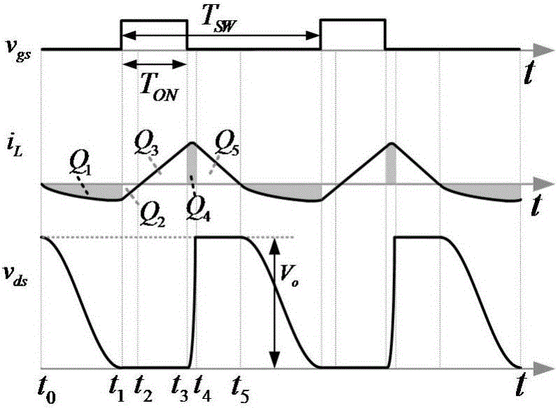
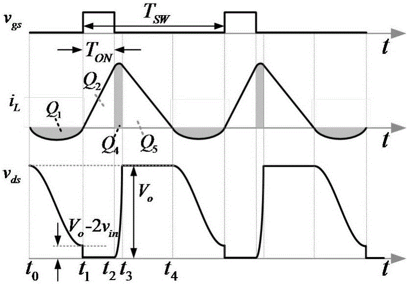
[0082] In order to obtain the changing conduction time curve (used in the look-up table method) that can realize the optimization of the input current THD of the CRM Boost PFC converter, it is necessary to analyze the working mode of the CRM Boost PFC converter. Picture 1-1 , Figure 1-2 In order to consider the resonance process between the boost inductor and the parasitic capacitance of the power device (including the output junction capacitance of the switch tube and the equivalent parallel capacitance of the diode), the working waveform of the CRM Boost PFC converter includes the drive signal v of the switch tube gs , boost inductor current i L and the drain-to-source voltage v of the switch ds . in, Picture 1-1 It is the switching tube to achieve zero voltage turn...

Embodiment 2

[0112] Embodiment 2: A high-frequency CRM Boost PFC converter, and a method for generating a modulated wave signal that can realize its adaptive optimization of input current THD

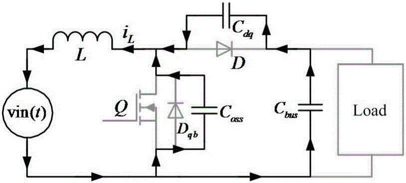
[0113] attached Figure 4 Shown is the structural block diagram of the high-frequency CRM Boost PFC converter that can adaptively optimize the input current THD. It is composed of the main circuit of the Boost PFC converter and the control circuit. It is characterized in that the control circuit adopts a combination of analog and digital control. The analog control circuit part includes an output voltage sampling circuit, an input voltage effective value sampling circuit, an input voltage zero-crossing detection circuit, a boost inductor current zero-crossing detection circuit, a switch tube shutdown signal generation circuit and a switch tube drive signal generation circuit; digital control The circuit part is a modulation wave signal generating circuit.

[0114] The highest switching frequency of...


PUM


Abstract

The invention provides a high-frequency CRM boost type PFC converter capable of adaptively optimizing the THD (total harmonic distortion) of input current and belongs to the AC-DC power conversion field. According to the high-frequency CRM boost type PFC converter, the THD (total harmonic distortion) of the input current is decreased based on a charge conduction time control mode; a digital table look-up mode is adopted to generate modulation wave signals, charge conduction time control is realized through a preset conduction time data table, and therefore, the problems of poor control precision and high cost of a digital real-time calculation mode of an analog control mode can be solved; all circuits except a modulation wave signal generating circuit, are realized by an analog mode, so that the defect that a digital controller is limited in MHz high-frequency signal response speed can be eliminated, and performance requirements for the digital controller can be lowered; preset limited data in the data table are transformed, so that the charge conduction time control can be adaptively adjusted with input voltage and output power with output power detection not required, and therefore, the THD (total harmonic distortion) of the input current can be adaptively optimized, and system cost can be significantly reduced.

Description

technical field [0001] The invention relates to a high-frequency CRM Boost PFC converter capable of adaptively optimizing input current THD, which belongs to the technical scope of power conversion, and in particular relates to the technical fields of high-quality AC-DC power conversion and high-frequency power conversion. Background technique [0002] The wide application of power electronic devices in rectification occasions leads to a substantial increase in the harmonic content of the grid current and seriously endangers the normal and stable operation of the grid. The main hazards of harmonic current are as follows: a voltage drop occurs on the transmission line impedance, resulting in a non-sinusoidal grid voltage waveform; it is easy to interfere with the normal operation of adjacent electrical equipment, causing damage to electronic equipment, instruments and line protection devices, etc. Mismeasurement and malfunction; increase the additional loss and temperature ri...

Claims


Application Information

Patent Timeline
Patent Type & Authority Applications(China)
IPC IPC(8): H02M7/217H02M1/42H02M1/12
CPCH02M1/12H02M1/4225H02M1/4241H02M7/217H02M1/0012Y02B70/10
Inventor 任小永郭哲辉吴羽陈乾宏张之梁阮新波
Owner NANJING UNIV OF AERONAUTICS & ASTRONAUTICS
Why Eureka
Try Eureka