Vibration energy collector

A vibration energy harvesting, mass block technology, applied in the direction of generator/motor, piezoelectric effect/electrostrictive or magnetostrictive motor, electrical components, etc., can solve the problem of low frequency point energy density, unfavorable energy harvesting, resonance Problems such as narrow bandwidth at frequency

Active Publication Date: 2017-01-18
SYSU CMU SHUNDE INT JOINT RES INST +1
View PDF5 Cites 12 Cited by
  • Summary
  • Abstract
  • Description
  • Claims
  • Application Information

AI Technical Summary

Problems solved by technology

The traditional vibration energy harvester has the following problems: (1) It has a single resonance frequency point, which is not conducive to energy collection; (2) The bandwidth at the resonance frequency is narrow, and more energy cannot be collected; (3) The energy density of the frequency point lower

Method used


Image

  • Vibration energy collector
  • Vibration energy collector

Examples


Embodiment 1

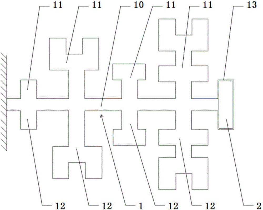
[0023] like figure 1 As shown, the vibration energy harvester described in this embodiment includes a piezoelectric cantilever beam 1 and a mass block 2, and the piezoelectric cantilever beam 1 includes a horizontally arranged main beam 10 and a plurality of longitudinally arranged first subbeams 11 and a plurality of second secondary beams 12 arranged longitudinally, one end of the main beam 10 is a fixed end, the other end of the main beam 10 is a free end, and the mass block 2 is fixed on the free end of the main beam 10, A plurality of the first sub-beams 11 are arranged at intervals and fixed on one side of the main beam 10 , and a plurality of the second sub-beams 12 are arranged at intervals and fixed on the other side of the main beam 10 .

[0024] The above-mentioned vibration energy harvester applies an external force to the piezoelectric cantilever beam 1, which will cause the positive piezoelectric effect of the piezoelectric cantilever beam 1 to generate current. ...

Embodiment 2

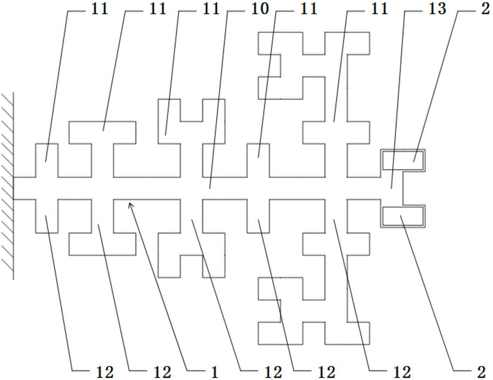
[0030] The difference between the vibration energy harvester described in the second embodiment and the vibration energy harvester described in the embodiment is that in the second embodiment, there are two mass blocks 2, and the two mass blocks 2 are respectively fixed on the installation beam 13 The two ends of the piezoelectric cantilever beam 1 are thus increased to generate more electric energy.

[0031] The number of the first sub-beams 11 is equal to the number of the second sub-beams 12, both of which are five. It should be noted that the number of the first sub-beams 11 is preferably 4-6, and the number of the second sub-beams 12 is preferably 4-6, so that there are enough resonant frequency points and the production difficulty is not high. high.


PUM


Abstract

The invention discloses a vibration energy collector. The collector comprises a piezoelectric cantilever beam and a mass block. The piezoelectric cantilever beam comprises a main beam which is transversely arranged, a plurality of first auxiliary beams which are vertically arranged and a plurality of second auxiliary beams which are vertically arranged. One end of the main beam is a fixed end. The other end of the main beam is a free end. The mass block is fixed to the free end of the main beam. The plurality of first auxiliary beams are arranged with intervals and are fixed to one side of the main beam. The plurality of second auxiliary beams are arranged with intervals and are fixed to the other side of the main beam. By using the vibration energy collector, the main beam of the piezoelectric cantilever beam is provided with the plurality of first auxiliary beams and the plurality of second auxiliary beams; each auxiliary beam possesses a respective resonant frequency and resonant frequency points of the vibration energy collector are increased; and when each auxiliary beam generates vibration, voltage attenuation of two sides of each resonant frequency point is slow so that a bandwidth is increased. Simultaneously, through the auxiliary beams, an electricity production area is correspondingly increased, output electric energy is improved and a problem that a frequency point energy density is low is solved.

Description

technical field [0001] The invention relates to the technical field, in particular to a vibration energy harvester. Background technique [0002] As the energy problem becomes more and more severe, it has become a hot research topic to seek a system that can collect the surrounding environmental energy and convert it into electrical energy. Mechanical vibration in the environment is ubiquitous, it is not affected by geographical location and climate, and there are vibration sources in many places that are difficult to enter, so the collection of vibration energy is more convenient and has a good development prospect. A vibration energy harvester is a device that converts mechanical energy generated by vibration into electrical energy. The traditional vibration energy harvester has the following problems: (1) It has a single resonance frequency point, which is not conducive to energy collection; (2) The bandwidth at the resonance frequency is narrow, and more energy cannot b...

Claims


Application Information

Patent Timeline
Patent Type & Authority Applications(China)
IPC IPC(8): H02N2/18
CPCH02N2/188
Inventor 高荣岗梁宏伟叶涛
Owner SYSU CMU SHUNDE INT JOINT RES INST
Why Eureka
Try Eureka