
Multi-arm coupled collision piezoelectric energy harvesting device

A piezoelectric energy collection device technology, applied in piezoelectric effect/electrostrictive or magnetostrictive motors, electrical components, generators/motors, etc., can solve the problem of low energy collection efficiency, narrow frequency bandwidth, and resonance frequency Single and other problems, to achieve the effect of expanding the frequency bandwidth, increasing the resonant frequency point, and reducing the degree of damage

Active Publication Date: 2018-03-06
XIDIAN UNIV
View PDF6 Cites 0 Cited by
  • Summary
  • Abstract
  • Description
  • Claims
  • Application Information

AI Technical Summary

Problems solved by technology

[0006] The purpose of the present invention is to overcome the defects of the above-mentioned prior art, and propose a multi-arm coupling type collision piezoelectric energy harvesting device, which is used to solve the existing piezoelectric energy harvesting devices due to single resonance frequency and frequency bandwidth. Technical problem of low energy harvesting efficiency due to narrower

Method used


Image

  • Multi-arm coupled collision piezoelectric energy harvesting device
  • Multi-arm coupled collision piezoelectric energy harvesting device
  • Multi-arm coupled collision piezoelectric energy harvesting device

Examples


Embodiment 1

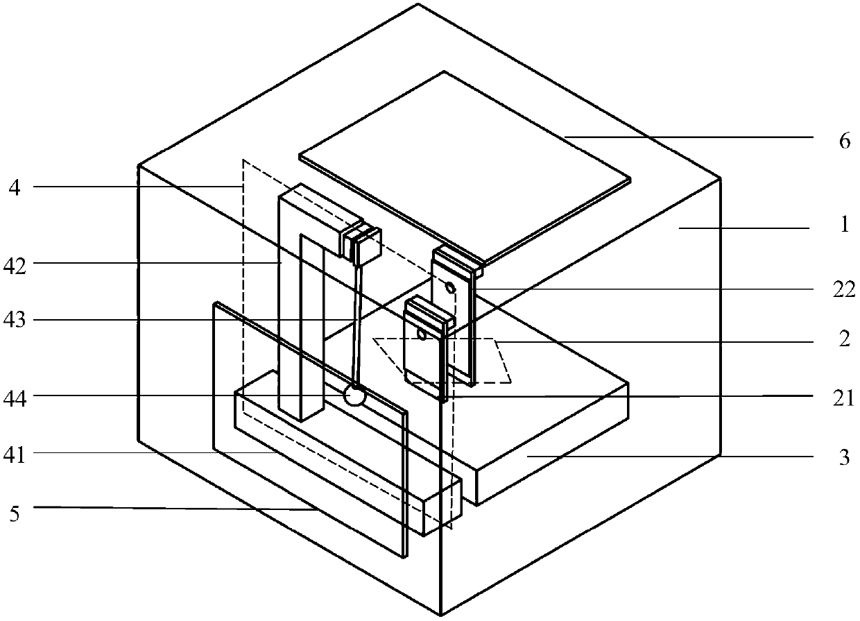
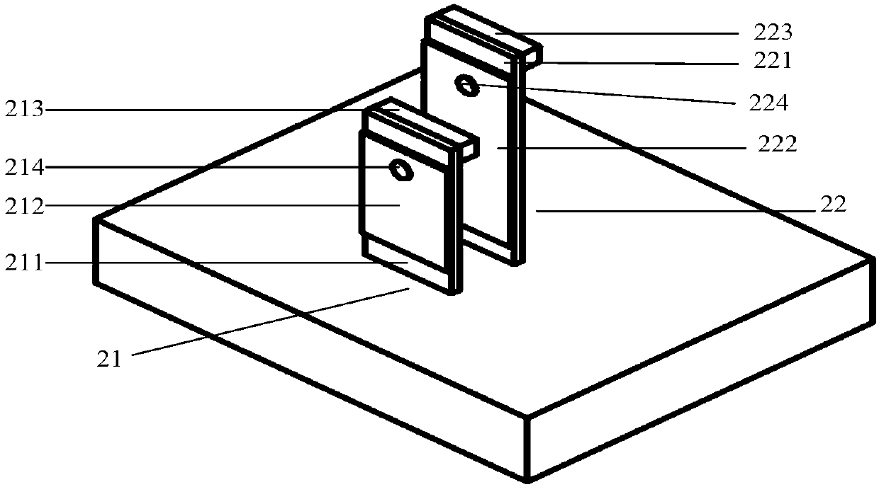
[0024] refer to figure 1 , the present invention includes: an outer frame 1, a piezoelectric vibrator 2, a first base 3, a pendulum structure 4, a first magnet 5 and a second magnet 6, wherein the piezoelectric vibrator 2 at least includes a first piezoelectric vibrator 21 and a The second piezoelectric vibrator 22 has a specific structure such as figure 2As shown, its bottom end is fixed on the first base 3. In order to make the first piezoelectric vibrator 21 or the second piezoelectric vibrator 22 resonate, the mutual coupling of vibration energy can be carried out by collision. The first piezoelectric vibrator The distance between 21 and the second piezoelectric vibrator 22 is smaller than the vibration amplitude when any piezoelectric vibrator resonates, in order to ensure that the first piezoelectric vibrator 21 and the second piezoelectric vibrator 22 have a larger coupling coefficient when coupling, the piezoelectric vibrator The arrangement of the electric vibrator ...

Embodiment 2

[0027] Embodiment 2: Embodiment 2 has the same structure as Embodiment 1, only the length of the swing rod 43 is adjusted, so that the impact ball 44 in the single pendulum structure 4 can hit the free space of the second piezoelectric vibrator 22 during the swing process. end.

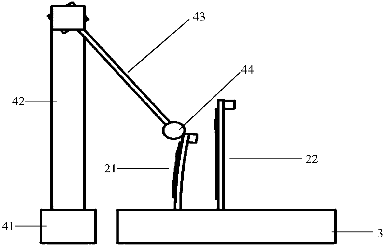
[0028] refer to Figure 4 , when the vibration in the direction perpendicular to the swing rod 43 is sensed, the impact ball 44 starts to swing, and during the swing process, it collides with the second piezoelectric vibrator 22 to complete the energy transfer, and the energy transfer process conforms to the law of energy conservation . After the collision, the second piezoelectric vibrator 22 vibrates at its natural frequency to generate mechanical deformation and implement the piezoelectric effect, so that the second electrode 224 has a voltage output and realizes the conversion of mechanical energy into electrical energy; when the second piezoelectric vibrator 22 When it reaches the resonance sta...


PUM


Abstract

The invention provides a multi-arm coupled collision piezoelectric energy collection device and is intended to solve the technical problem that an existing piezoelectric energy collection device has low energy collection efficiency; the multi-arm coupled collision piezoelectric energy collection device comprises an outer frame, piezoelectric vibrators, a first base, a simple pendulum structure, a first magnet and a second magnet; the piezoelectric vibrators at least include a first piezoelectric vibrator and a second piezoelectric vibrator, the bottom ends of the vibrators are fixed to the first base and may generate high mutual coupling upon resonance, the simple pendulum structure comprises a second base, a link, a rocker and a striker ball, the bottom end of the link is fixed to the second base, the top end of the link is movably connected with the upper end of the rocker, the striker ball is fixed to the lower end of the rocker, and the striker ball may collide with the free end of the first piezoelectric vibrator or second piezoelectric vibrator while rocking, the first base and the second base are fixed to the bottom of the outer frame, the side of the outer frame close to the simple pendulum structure is fixedly provided with the first magnet, and the top of the outer frame close to the piezoelectric vibrators is fixedly provided with the second magnet. The multi-arm coupled collision piezoelectric energy collection device has effectively improved energy collection efficiency.

Description

technical field [0001] The invention belongs to the field of energy collection, and relates to an energy collection device, in particular to a multi-arm coupling type collision piezoelectric energy collection device, which can be used to convert mechanical energy in the environment into electric energy. Background technique [0002] Energy harvesting devices are able to harvest energy from the surrounding environment and convert it into electricity. Using energy harvesting devices to power equipment or circuits, compared with traditional battery-powered methods, can reduce maintenance costs caused by battery replacement and work failures caused by battery exhaustion. [0003] At present, energy harvesting devices can be divided into three categories: photovoltaic energy harvesting devices, thermoelectric energy harvesting devices, and piezoelectric energy harvesting devices, according to the objects and principles of collection and transformation. Among them, the piezoelect...

Claims


Application Information

Patent Timeline
Patent Type & Authority Patents(China)
IPC IPC(8): H02N2/18
CPCH02N2/188
Inventor 王海王柯胡丰毛敏泉赵伟
Owner XIDIAN UNIV
Learn More