Variable dielectric constant-based antenna and array

a dielectric constant and variable technology, applied in the direction of waveguide type devices, resonant antennas, radiating element structural forms, etc., can solve the problems of high overall antenna cost, high cost of phase shifters, and greatly diminishing antenna efficiency, and achieve high conversion efficiency

Active Publication Date: 2008-12-16
HAZIZA DEDI DAVID D +3
View PDF9 Cites 112 Cited by
  • Summary
  • Abstract
  • Description
  • Claims
  • Application Information

AI Technical Summary

Benefits of technology

[0020]According to aspects of the invention, there is provided a novel scanning antenna array having radiating elements which provides high conversion efficiency, while being small, simple, and inexpensive to manufacture.

Problems solved by technology

With micro-strip technology, antenna efficiency greatly diminishes as the size of the antenna increases.
However, phase shifters are costly and, particularly if the phased array incorporates many elements, the overall antenna cost can be quite high.
Also, phase shifters require separate, complex control circuitry, which translates into unreasonable cost and system complexity.
While that antenna is said to have a low profile—extending to a height of “only” 14 inches without the radome (radar dome)—its size may be acceptable for military applications, but not acceptable for consumer applications, e.g., for private automobiles.
Current mobile systems are expensive and complex.
In practical consumer products, size and cost are major factors, and providing a substantial reduction of size and cost is difficult.
In addition to the cost, the phase shifters of known systems inherently add loss to the respective systems (e.g., 3 dB losses or more), thus requiring a substantial increase in antenna size in order to compensate for the loss.
In a particular case, such as a DBS antenna system, the size might reach 4 feet by 4 feet, which is impractical for consumer applications.
Current antenna systems are relatively too large for commercial use, have problems with collection efficiency, and are priced in the thousands, or even tens of thousands of dollars, thereby being way beyond the reach of the average consumer.
Some patch antennas eschew a substrate and suspend a metal patch in air above a ground plane using dielectric spacers; the resulting structure is less robust but provides better bandwidth.
This reduces the rotation of the polarization of the incident light, and the device appears gray.

Method used


Image

  • Variable dielectric constant-based antenna and array
  • Variable dielectric constant-based antenna and array
  • Variable dielectric constant-based antenna and array

Examples


Embodiment Construction

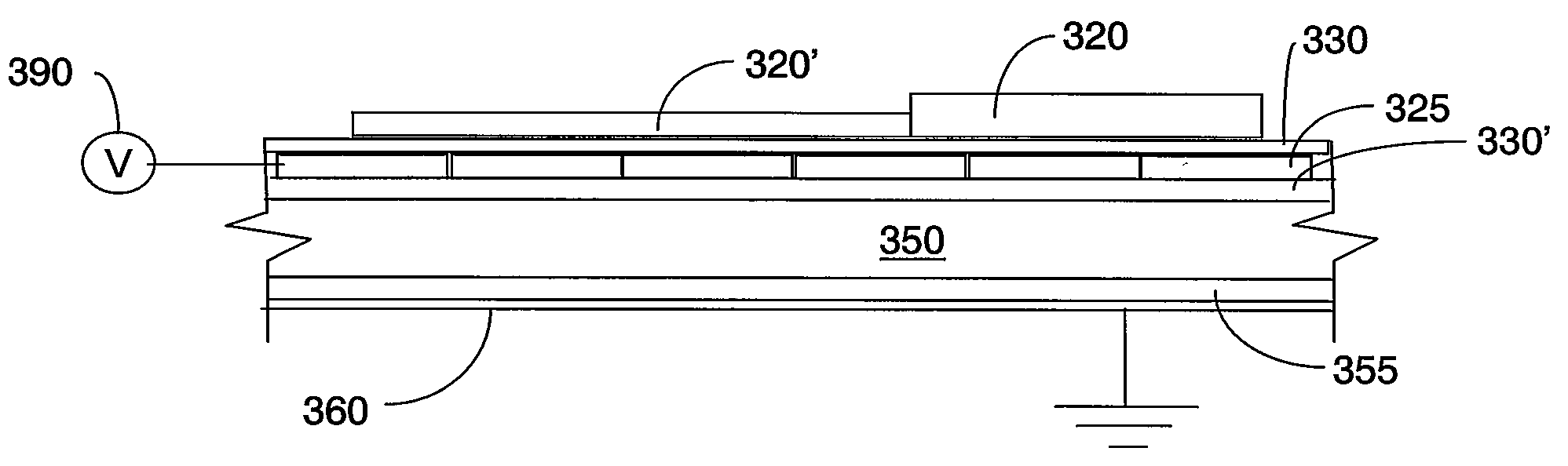
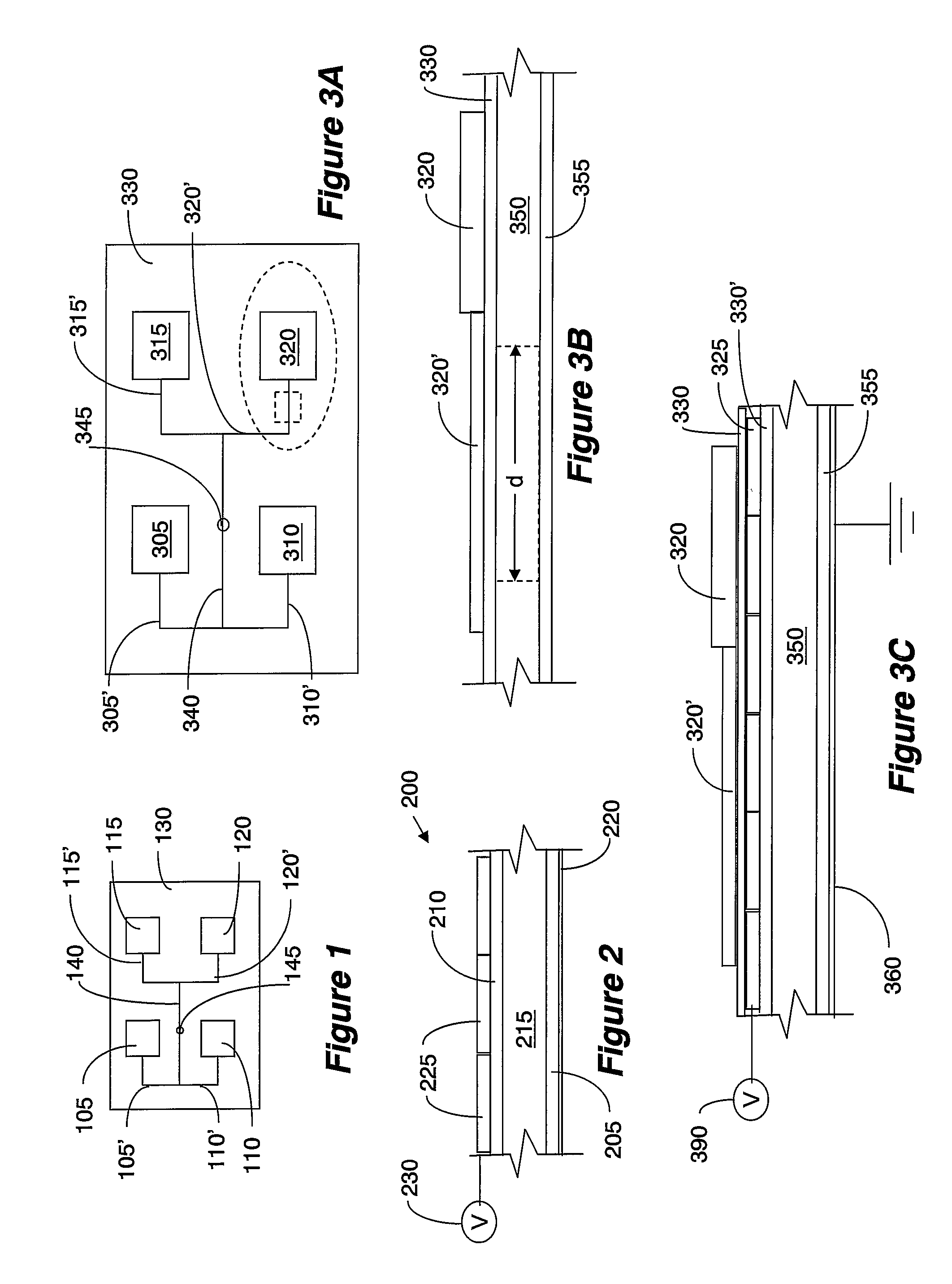
[0035]Various embodiments of the invention are generally directed to a structure of radiating elements and their feed lines provided over an LCD structure, and a scanning antenna array and systems incorporating such a structure. In the context of the description of the various embodiments, the LCD structure used for the inventive antenna need not include a lighting source. The various embodiments described herein may be used, for example, in connection with stationary and / or mobile platforms. Of course, the various antennas and techniques described herein may have other applications not specifically mentioned herein. Mobile applications may include, for example, mobile DBS or VSAT integrated into land, sea, or airborne vehicles. The various techniques may also be used for two-way communication and / or other receive-only applications.

[0036]FIG. 3A depicts an example of a scanning antenna according to an embodiment of the invention, while FIG. 3B depicts a cross section of an enlarged ...


PUM

PropertyMeasurementUnit
heightaaaaaaaaaa
sizeaaaaaaaaaa
dielectric constantaaaaaaaaaa

Abstract

An antenna and antenna array are provided. A radiating elements and corresponding feed lines are provided over a variable dielectric constant material sandwiched between two panels. The sandwich may be in the form of an LCD. The dielectric constant in a selected area under the conductive line can be varied to control the phase of the radiating element. The dielectric constant in a selected area under the radiating element can be varied to control the resonance frequency of the radiating element. The dielectric constant in a selected area under the conductive line can be varied to also control the polarization of the radiating element.

Description

CROSS-REFERENCE TO RELATED APPLICATIONS[0001]This Application is a continuation of and claims priority from U.S. application Ser. No. 60 / 808,187, filed May 24, 2006; U.S. application Ser. No. 60 / 859,667, filed Nov. 17, 2006; U.S. application Ser. No. 60 / 859,799, filed Nov. 17, 2006; U.S. application Ser. No. 60 / 890,456, filed Feb. 16, 2007; and U.S. application Ser. No. 11 / 695,913, filed Apr. 3, 2007, the disclosures of all of which are incorporated herein by reference in their entirety.BACKGROUND[0002]1. Field of the Invention[0003]The general field of the invention relates to a unique electromagnetic antenna which can be used for radiating and non-radiating electromagnetic devices. Embodiments of the invention relate generally to antenna structures and, more particularly, to antenna structure having a radiating element structured on LCD, and to antenna having an array of such radiating elements.[0004]2. Related Arts[0005]Various antennas are known in the art for receiving and tran...

Claims


Application Information

Patent Timeline
Patent Type & Authority Patents(United States)
IPC IPC(8): H01Q1/38
CPCH01Q3/36H01Q9/0442H01Q3/44Y10T29/49016
Inventor HAZIZA, DEDI DAVID
Owner HAZIZA DEDI DAVID D
Why Eureka
Try Eureka