
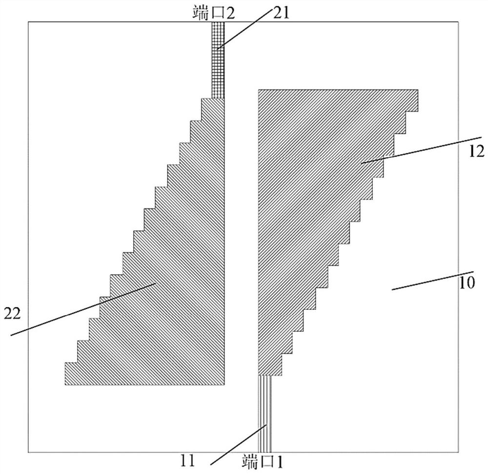
Beveled edge step change triangular metal radiation patch multi-frequency microstrip MIMO antenna

A technology of radiation patch and step change, applied in the field of wireless communication, can solve the problems of low radiation gain of multi-stub antenna, complex structure of multi-frequency antenna, single working frequency of plane antenna, etc., so as to improve isolation and reduce port coupling. The effect of coefficients

Pending Publication Date: 2021-03-12
YULIN UNIV
View PDF0 Cites 0 Cited by
  • Summary
  • Abstract
  • Description
  • Claims
  • Application Information

AI Technical Summary

Problems solved by technology

[0005] The purpose of the present invention is to provide a multi-frequency triangular metal radiation patch with step-change hypotenuse in view of the above-mentioned problems in the prior art that the planar antenna has a single operating frequency point, the structure of the multi-frequency antenna is too complicated, and the radiation gain of the multi-twig antenna is low. Microstrip MIMO antenna, extending the resonant frequency point of the antenna, improving the isolation between antenna elements and the remote radiation gain

Method used


Image

  • Beveled edge step change triangular metal radiation patch multi-frequency microstrip MIMO antenna
  • Beveled edge step change triangular metal radiation patch multi-frequency microstrip MIMO antenna
  • Beveled edge step change triangular metal radiation patch multi-frequency microstrip MIMO antenna

Examples


Embodiment Construction

[0019] The present invention will be further described in detail below in conjunction with the accompanying drawings and embodiments.

[0020] In order to solve the problems of a single resonant frequency point of the microstrip MIMO antenna, too low port isolation of the multi-frequency MIMO antenna, and low remote radiation gain in the frequency band, the two-element microstrip MIMO antenna designed by the present invention uses a right triangle as the main radiation patch and the hypotenuse of the right-angled triangle facing the outside is in the form of a step (step) change, turning an ordinary two-element microstrip MIMO antenna into a three-band, high isolation, and high far-field radiation gain two-element micro With MIMO antenna. According to the resonant frequency point, the two-unit MIMO antenna can be applied in 5G wireless mobile communication system.

[0021] see Figure 1-3 , the antenna of the present invention has a rectangular dielectric substrate 10 . The...


PUM


Abstract

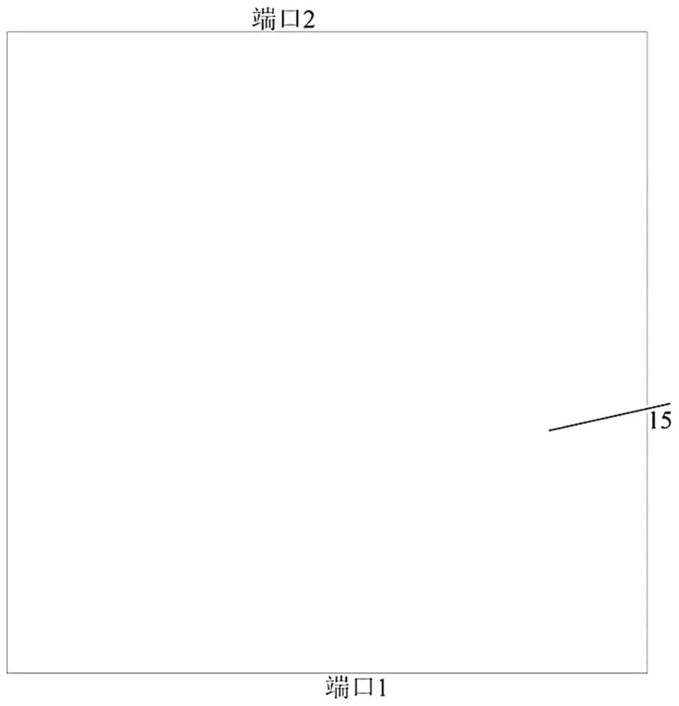
A beveled edge step change triangular metal radiation patch multi-frequency microstrip MIMO antenna comprises two identical antenna units arranged on a rectangular dielectric substrate, and a feed structure and a radiation structure of a first antenna unit and a second antenna unit etched on the upper surface of the rectangular dielectric substrate. The lower surface of the rectangular dielectricsubstrate is covered with metal to form a common grounding plate of the first antenna unit and the second antenna unit, the feed structure is a rectangular microstrip feed transmission line extendinginwards from the edge of the rectangular dielectric substrate, and the radiation structure is a right-angled triangle radiation patch. One right-angled side of the right-angled triangle radiation patch and the rectangular microstrip feed transmission line are located on a same straight line, the hypotenuse of the right-angled triangle radiation patch is in step change and is arranged towards the outer side, and the two antenna units are rotationally symmetrical. According to the invention, the resonance frequency point of the antenna is expanded, and the isolation degree between the antenna units and the remote radiation gain are improved.

Description

technical field [0001] The invention belongs to the field of wireless communication, in particular to a triangular metal radiation patch multi-frequency microstrip MIMO antenna with a hypotenuse step change. Background technique [0002] Although the fifth-generation mobile communication technology and the fourth-generation mobile communication are only optimized in three aspects: data transmission rate, network capacity and delay. but. 5G mobile communication supports a user experience rate of 0.1-1Gpbs, a connection density of one million per square kilometer, a millisecond-level end delay, a traffic density of 10Tbps per square kilometer, a mobile performance of more than 500km / h and a peak value of 20Gbps rate. Compared with the 4G mobile communication system, the above indicators are not minor quantitative changes, but fundamental qualitative changes. According to ITU-R (International Telecommunication Union Radiocommunication Sector), three application scenarios of ...

Claims


Application Information

Patent Timeline
IPC IPC(8): H01Q1/52H01Q1/38H01Q5/28H01Q9/04
CPCH01Q1/521H01Q1/38H01Q5/28H01Q9/0407
Inventor 李海雄赵鹏郑欢欢张宇航李鹏
Owner YULIN UNIV
Learn More