Dual feel multi-band planar antenna

a multi-band, planar antenna technology, applied in the field of antennas, can solve the problems of multi-band pifa with multiple antenna feed ports may have its performance compromised, and complex antenna design

Inactive Publication Date: 2003-12-30
LAIRD CONNECTIVITY LLC
View PDF8 Cites 176 Cited by
  • Summary
  • Abstract
  • Description
  • Claims
  • Application Information

AI Technical Summary

Benefits of technology

On the other hand, a multi-band PIFA having multiple antenna feeds tends to diminish antenna design complexities since the design of a plurality of individual radiating / receiving elements, each having a separate feed, tends to be less difficult. However, multiple antenna feeds encounter the problem of mutual coupling between the individual radiating / receiving elements of a multi-band. PIFA. There is also a concern that a multi-band PIFA with multiple antenna feed ports may have its performance compromised due to mutual coupling and poor isolation between the PIFA's various resonant bands.
Further improvement in the isolation that is provided by a dual-feed. dual-band, PIFA has been realized by increasing the physical separation between the antenna's multiple radiating / receiving elements. However, such an option contradicts the desirable requirement that the overall physical volume that is occupied by the PIFA be small.
To the contrary, the present invention improves the isolation (18-19 dB) between the two feed ports of two-antenna assemblies that are constructed and arranged in accordance with the present invention, without degrading the gain at the individual antenna ports. Further, the present invention does not increase the overall physical volume that is occupied by the multi-band antenna structure.

Problems solved by technology

In a single antenna feed, multi-band, PIFA providing a required bandwidth at multiple resonant frequencies generally leads to antenna design complexities.
However, multiple antenna feeds encounter the problem of mutual coupling between the individual radiating / receiving elements of a multi-band.
There is also a concern that a multi-band PIFA with multiple antenna feed ports may have its performance compromised due to mutual coupling and poor isolation between the PIFA's various resonant bands.
Hence, in spite of the reduced design complexities that are provided by a multi-band PIFA having multiple feeds, such a PIFA has not been a choice for practical applications, mainly due to the mutual coupling problem.
However, most of the prior art dual-feed, dual-band, PIFAs exhibit an isolation of only about 15 dB.
However, such an option contradicts the desirable requirement that the overall physical volume that is occupied by the PIFA be small.
Any improvement in the isolation, while maintaining the overall volume of the PIFA, is at the expense of gain at one of the antenna ports.
The problem of mutual coupling within a dual-feed, multi-band, PIFA is a severe constraint or drawback for the utility of such an antenna in system applications.
In view of an emphasis on reducing the physical size of internal cellular antennas, this recourse of providing an increased physical separation between the radiating / receiving elements is not a practical solution.

Method used


Image

  • Dual feel multi-band planar antenna
  • Dual feel multi-band planar antenna
  • Dual feel multi-band planar antenna

Examples


Embodiment Construction

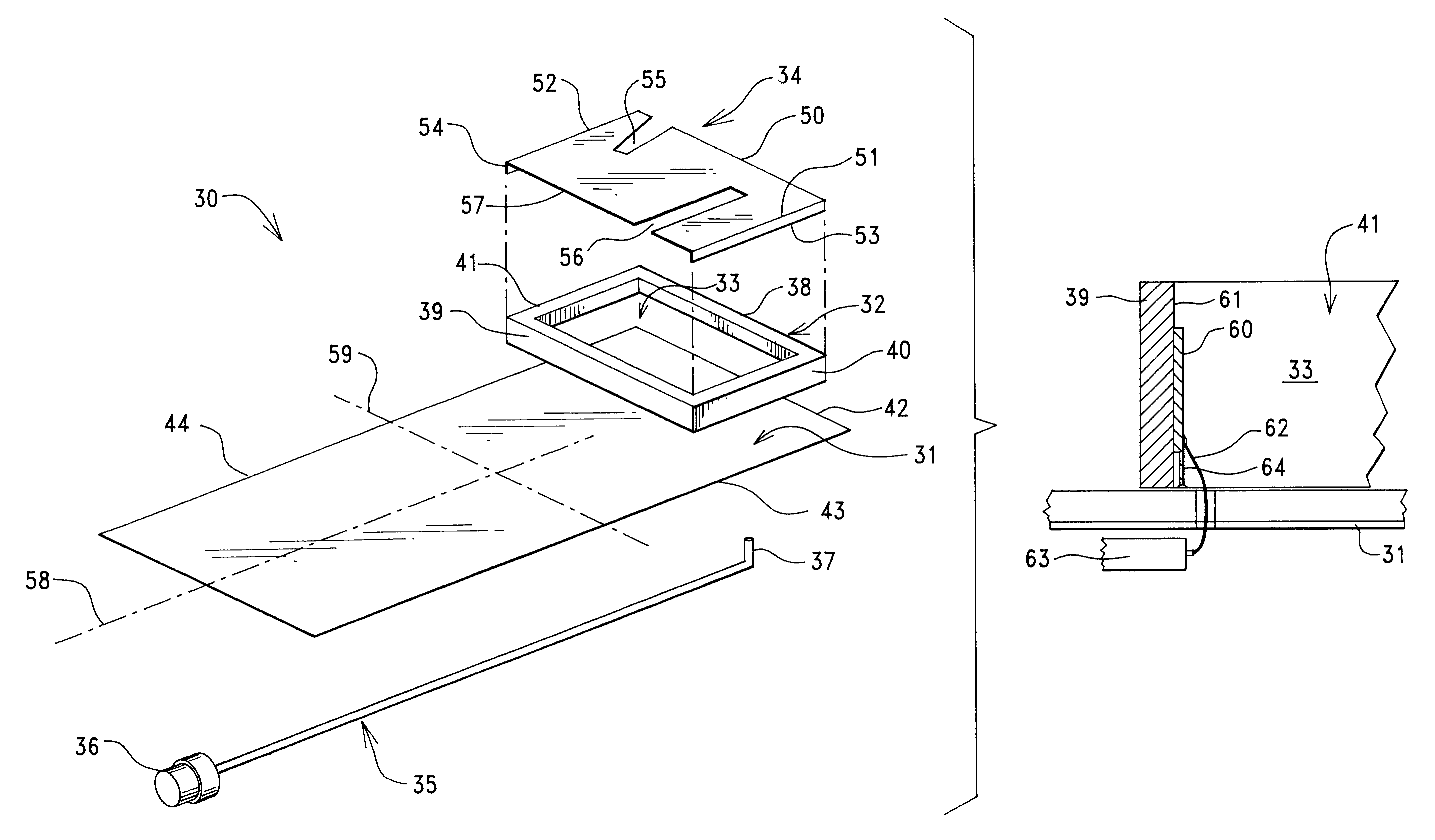
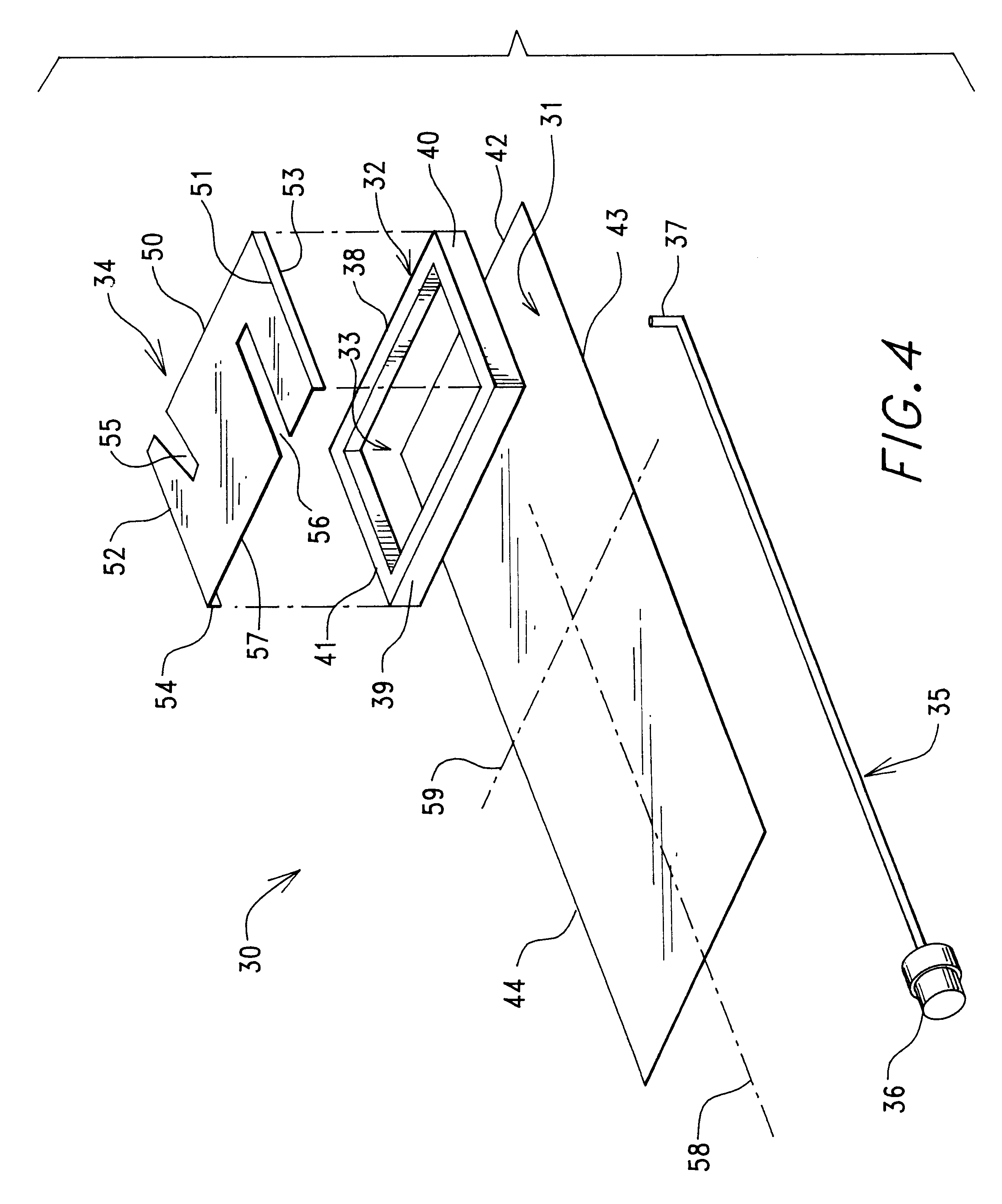
FIG. 4 is an exploded top and side view that shows only the PIFA portion 30 of a two-antenna assembly that is constructed and arranged in accordance with the present invention.

PIFA 30 includes four basic structural elements, i.e. (1) a rectangular, flat and metallic ground plane element 31, (2) a four-wall, box-shaped and relatively rigid dielectric carriage 32 whose four walls 38-41 define a box-shaped open cavity 33, (3) a generally flat and metallic radiating / receiving element 34, and (4) a coaxial feed cable 35 having an RF connector 36 at one end and an exposed and upward-extending centrally located metal conductor 37 at the other end.

The four side edges of radiating / receiving element 34 rest on and are physically supported by the top surface of the four walls 38-41 of dielectric carriage 32, such that a plane that is occupied by radiating / receiving element 34 is generally parallel to a plane that is occupied by ground plane element 31.

Ground plane element 31 is in the form of ...


PUM


Abstract

A three-band, two-antenna, assembly includes a planar inverted-F antenna (PIFA) having a radiating / receiving element that is spaced from and extends generally parallel to a ground plane element. The planar radiating / receiving element of an inverted-F antenna (IFA) is located in an open space that exists between the radiating / receiving element of the PIFA and the ground plane element. The radiating / receiving element of the IFA extends either perpendicular to, or parallel to, the radiating / receiving element of the PIFA. The radiating / receiving element of the PIFA includes one or more open slot configurations that operate to provide dual resonant frequencies for the IPFA (AMPS / PCS or GSM / DCS). The radiating / receiving element of the IFA operates in a non-cellular frequency band (ISM or GPS).

Description

1. Field of the InventionThis invention relates to antennas, and more specifically to antennas for use within handheld or portable wireless communication devices or handsets.2. Description of the Related ArtState of the art cellular communication systems generally require handsets that provide both a multi-band and a multi-system capability. That is, there is a growing need for multi-purpose cellular handsets that can be utilized in cellular applications such as Advanced-Mobile-Phone-Service (AMPS), Personal-Communications-Service (PCS), Global-System-For-Mobile-Communication (GSM), Distributed-Communications-System (DCS) and Industrial Scientific Medical (ISM), and that can also be utilized in non cellular applications such as Global-Positioning-System (GPS) and Bluetooth (BT) (Bluetooth is the code name for an open specification to standardize data synchronization between disparate personal computer and handheld personal computer devices).Current advances in cellular communication...

Claims


Application Information

Patent Timeline
Patent Type & Authority Patents(United States)
IPC IPC(8): H01Q13/10H01Q1/24H01Q21/29H01Q21/00H01Q21/30H01Q9/04H01Q21/28
CPCH01Q1/243H01Q9/0414H01Q9/0421H01Q21/30H01Q21/28H01Q21/29H01Q13/10H01Q1/38H01Q5/307
Inventor KADAMBI, GOVIND RANGASWAMYSTOILJKOVIC, VLADIMIRSUGANTHAN, SHANMUGANATHAN
Owner LAIRD CONNECTIVITY LLC
Why Eureka
Try Eureka