Microstrip antenna

a microstrip antenna and antenna technology, applied in the direction of resonant antennas, substantially flat resonant elements, radiating element structural forms, etc., can solve the problems of reducing affecting the performance of stacked patches, and limiting the linear polarization range. , to achieve the effect of improving impedance matching, wide bandwidth, and flexible feed network options

Inactive Publication Date: 2011-08-09
HARADA IND OF AMERICA
View PDF22 Cites 183 Cited by
  • Summary
  • Abstract
  • Description
  • Claims
  • Application Information

AI Technical Summary

Benefits of technology

[0012]An advantage of the antenna of the present invention is that a single feed point is all that is required in the cross-shaped feed network while still providing dual-frequency and dual-polarization capability. Another advantage, associated with the multi-feed embodiment, is that there is flexibility in the feed network option. One feed may be physically connected and another feed is capacitively coupled, thereby improving impedance matching and providing a wider bandwidth than a direct feed to the ring patch.
[0013]Another advantage, applicable to either feed network, is that the antenna operates at dual frequencies. The radiating elements are co-planar. However, the inner radiating element operates at one frequency while the outer radiating element operates at a different frequency. Yet another advantage is that the antenna can be linearly, co-circularly, or dual-circularly polarized.
[0014]The feed network, consisting of a single cross-shaped feed line, excites both horizontal and vertical radiating apertures of the inner and outer radiating elements, thereby providing dual polarization capabilities. The feed network, consisting of multiple feed point locations provides flexibility in selecting the polarization and increases isolation between the radiating elements. The multiple feed point locations can accommodate either center fed or diagonal fed configurations for the microstrip antenna.

Problems solved by technology

Further, the stacked patches are also subject to decreased performance.
Therefore, the gain and beam width of the antenna may be compromised.
However, interference is a concern with co-planar microstrip antennas.
Most co-planar microstrip antennas incorporate slots for obtaining dual-band operation, yet are limited to linear polarization, and have limited bandwidth and gain characteristics.

Method used


Image

  • Microstrip antenna
  • Microstrip antenna
  • Microstrip antenna

Examples


Embodiment Construction

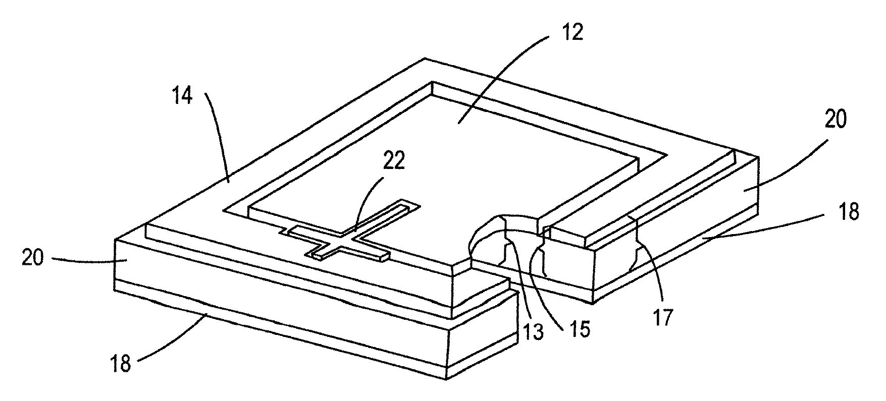
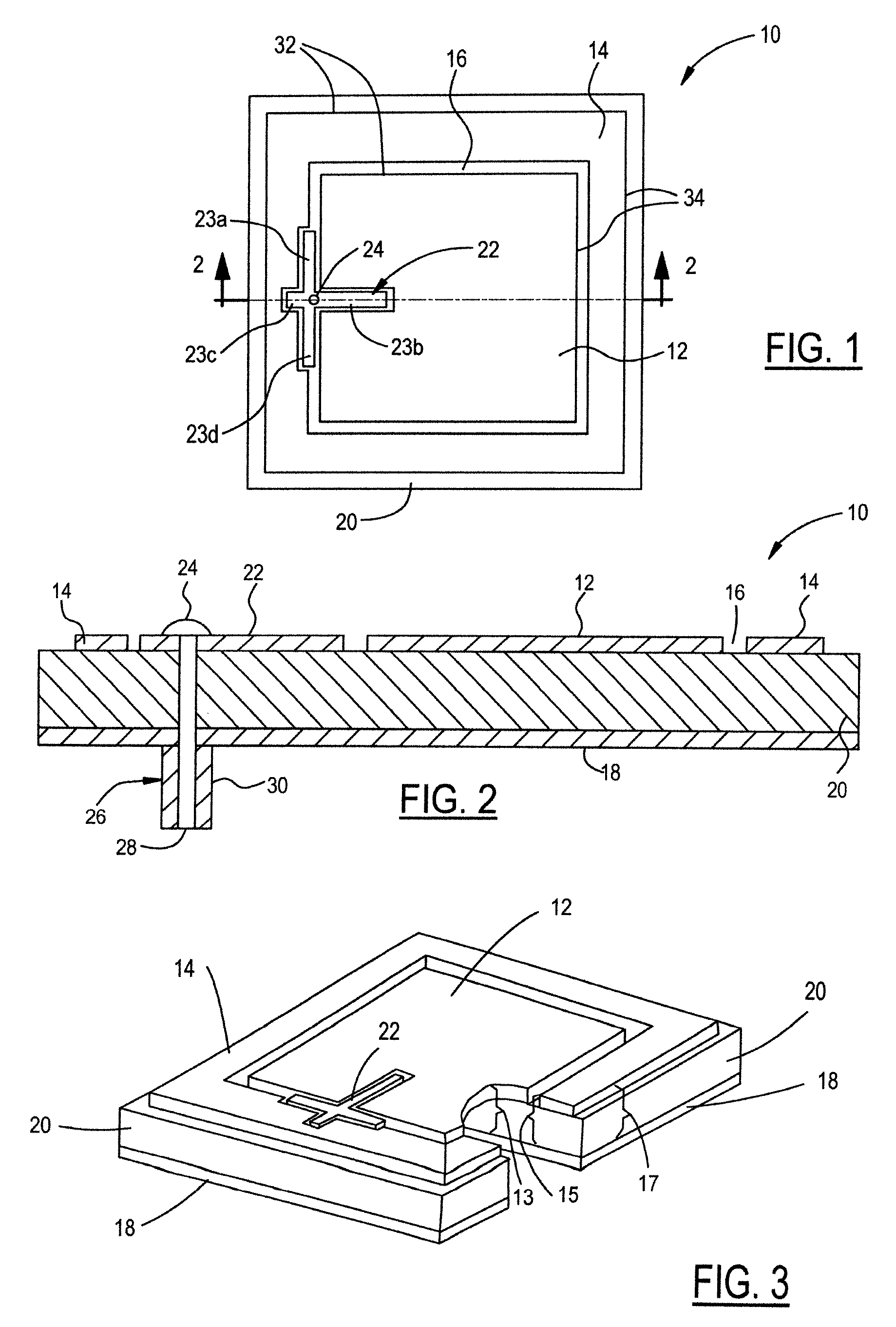
[0026]FIG. 1 is a plane view of one embodiment of a microstrip antenna shown generally at 10 and FIG. 2 is a cross-sectional view of the embodiment in FIG. 1 as taken along the line 2-2 in FIG. 1. Hereinafter, like reference numerals in each of the drawings reflect like elements. The antenna 10 has an inner radiating element 12 and an outer radiating element 14, both are microstrip patch elements. The inner radiating element 12 is nested within and co-planar to the outer radiating element 14. A feed network shown generally at 22 feeds inner and outer radiating elements 12, 14 at a single point by a feed pin 24. The inner and outer radiating elements 12 and 14 are separated from each other by a separation 16, which generally mimics the shape of each of the inner and outer radiating elements 12, 14 and the shape of the feed network 22. Referring to FIG. 2, a conductive ground plane 18 is spaced from the inner and outer radiating elements by a dielectric material 20. The dielectric mat...


PUM


Abstract

A microstrip antenna that can be linear, co-circular, or dual-circularly polarized having co-planar radiating elements and operating at dual frequency bands wherein an inner radiating element is surrounded by and spaced from an outer radiating element. Each radiating element resonates at a different frequency. In one embodiment of the invention a feed network has a single, cross-shaped, feed line that is positioned between the inner and outer radiating elements and capacitively coupled to the inner and outer radiating elements. In another embodiment of the present invention, the radiating elements are fed separately by first and second feed networks each having a plurality of feed points. The radiating elements each have one active feed point that is either directly or indirectly coupled to its respective feed network.

Description

TECHNICAL FIELD[0001]The present invention relates generally to a microstrip antenna and more particularly to a microstrip antenna having dual polarization and dual frequency capability.BACKGROUND OF THE INVENTION[0002]A microstrip antenna is typically comprised of a conductive plate, also known as a patch or a radiating element, that is separated from a ground plane by a dielectric material. The microstrip antenna is fed by applying a voltage difference between a point on the radiating element and a point on the ground conductor. Feed methods include direct feed such as probes or transmission lines and indirect feed such as capacitive coupling.[0003]Microstrip antennas have a low profile, are light weight, are easy to fabricate and therefore, are relatively low cost. These advantages have encouraged the use of microstrip antennas in a wide variety of applications. In the automotive industry in particular, microstrip antennas are used on vehicles for receiving signals transmitted by...

Claims


Application Information

Patent Timeline
Patent Type & Authority Patents(United States)
IPC IPC(8): H01Q13/10H01Q5/00H01Q1/38H01Q5/40
CPCH01Q9/0407H01Q9/0428H01Q5/40H01Q9/045H01Q9/0435
Inventor MAEDA, HIROYUKIDAI, YINGCHENG
Owner HARADA IND OF AMERICA
Why Eureka
Try Eureka