Multi-frequency double-layer dielectric plate feed source patch and radiation slot complementary microstrip antenna

A technology of microstrip antenna and dielectric substrate, applied in the field of wireless communication, can solve the problems of increasing the resonant frequency of the antenna, complex antenna structure, and less resonant working frequency of the antenna, etc., so as to increase the current path, realize miniaturization, and good port matching. Effect

Active Publication Date: 2021-03-12
YULIN UNIV
View PDF10 Cites 1 Cited by
  • Summary
  • Abstract
  • Description
  • Claims
  • Application Information

AI Technical Summary

Problems solved by technology

[0007] The purpose of the present invention is to provide a multi-frequency double-layer dielectric plate feed source patch and radiation slot complementary microstrip antenna for the above-mentioned existing multi-frequency antenna technology with complex antenna structure and fewer antenna resonant operating frequency points. The complementary structure of the excitation patch and the radiation slot increases the resonant frequency of the antenna, simplifies the structure of the antenna, and reduces the profile of the antenna

Method used


Image

  • Multi-frequency double-layer dielectric plate feed source patch and radiation slot complementary microstrip antenna
  • Multi-frequency double-layer dielectric plate feed source patch and radiation slot complementary microstrip antenna
  • Multi-frequency double-layer dielectric plate feed source patch and radiation slot complementary microstrip antenna

Examples


Embodiment Construction

[0023] The present invention will be further described in detail below in conjunction with the accompanying drawings and embodiments.

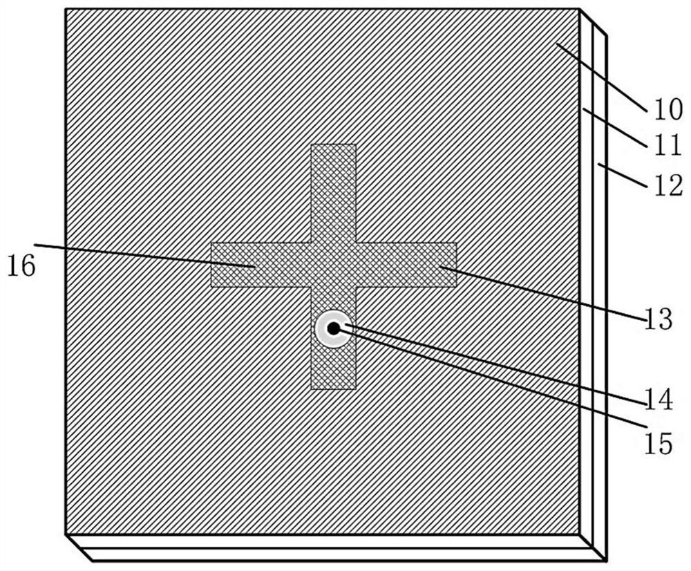
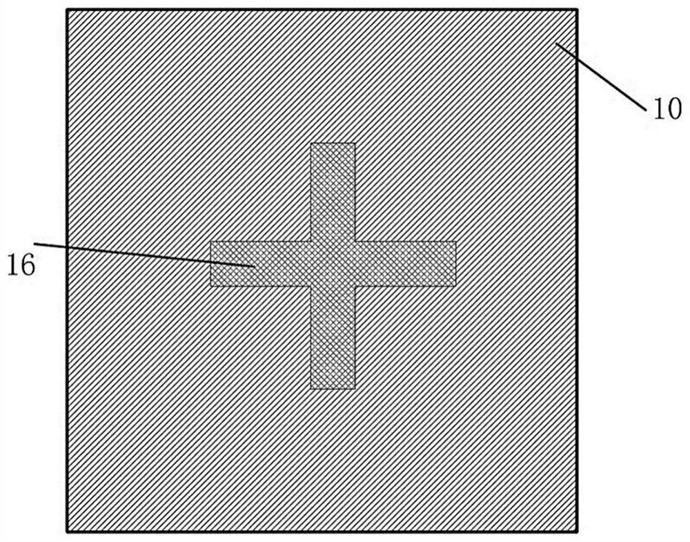
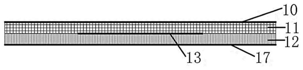
[0024] In order to solve the problems of single function caused by fewer resonant frequency points of the antenna, complex structure, increased cost and large processing error, large antenna volume seriously affects the miniaturization of the entire wireless communication device. The present invention proposes a multi-frequency double-layer dielectric board feed source patch and radiation slot complementary microstrip antenna. On the basis of the coaxial feed microstrip antenna structure, a rectangular dielectric substrate and a gap covering the upper surface of the dielectric substrate are added. metal patch. An ordinary single-frequency microstrip antenna is changed into a double-layer dielectric substrate microstrip antenna with five resonant frequency points, a simple structure, easy processing, low market cost, and miniaturization.

[00...


PUM

PropertyMeasurementUnit
lengthaaaaaaaaaa
widthaaaaaaaaaa
thicknessaaaaaaaaaa

Abstract

The invention discloses a multi-frequency double-layer dielectric plate feed source patch and radiation slot complementary microstrip antenna. The antenna comprises an upper dielectric substrate and alower dielectric substrate, a first rectangular metal patch is printed on the upper surface of the upper dielectric substrate, a cross-shaped gap is processed on the first rectangular metal patch, and a cross-shaped metal patch is printed on the upper surface of the lower dielectric substrate; the cross-shaped metal patch and the cross-shaped gap have the same geometric dimensions and correspondto each other up and down, a second rectangular metal patch is printed on the lower surface of the lower dielectric substrate to serve as a grounding plate, a circular non-metal area is machined on the second rectangular metal patch, the center of a non-metallized via hole coincides with the center of the circular non-metal area, and the radius of the non-metallized via hole is smaller than that of the circular non-metal area. By adopting the structure that an excitation patch and a radiation slot are complementary, the resonant frequency points of the antenna are increased, the structure of the antenna is simplified, and the profile of the antenna is reduced.

Description

technical field [0001] The invention belongs to the field of wireless communication, and in particular relates to a multi-frequency double-layer dielectric board feed source patch and a radiation slot complementary microstrip antenna. Background technique [0002] With the development of science and technology and social progress, the radio communication system is also constantly developing. As an important member of the wireless communication system, the antenna needs to realize the radiation and reception of wireless electromagnetic waves, that is, to convert the energy in the form of current conduction in the transmission line into the energy in the form of space electromagnetic radiation. [0003] The miniaturization of equipment has been the development direction of wireless mobile communication equipment for many years. The reduction of the volume of the equipment requires the volume of each device in the equipment to be reduced, and in most wireless communication equ...

Claims


Application Information

Patent Timeline
Patent Type & Authority Applications(China)
IPC IPC(8): H01Q1/38H01Q9/04H01Q1/50H01Q13/08H01Q13/10
CPCH01Q1/38H01Q9/0407H01Q13/106H01Q1/50H01Q13/08Y02D30/70
Inventor 李海雄王建强吴敏宁强国柱
Owner YULIN UNIV
Why Eureka
Try Eureka