Data transmission method and system

A data transmission method and data technology, applied in transmission systems, radio transmission systems, diversity/multi-antenna systems, etc., to achieve the effects of reducing complexity, improving accuracy, and increasing access speed

Active Publication Date: 2017-03-01
ZTE CORP
View PDF4 Cites 37 Cited by
  • Summary
  • Abstract
  • Description
  • Claims
  • Application Information

AI Technical Summary

Problems solved by technology

[0007] In order to solve the above-mentioned technical problems, the present invention provides a data transmission method and system, wh...

Method used


Image

  • Data transmission method and system
  • Data transmission method and system
  • Data transmission method and system

Examples


Embodiment 1

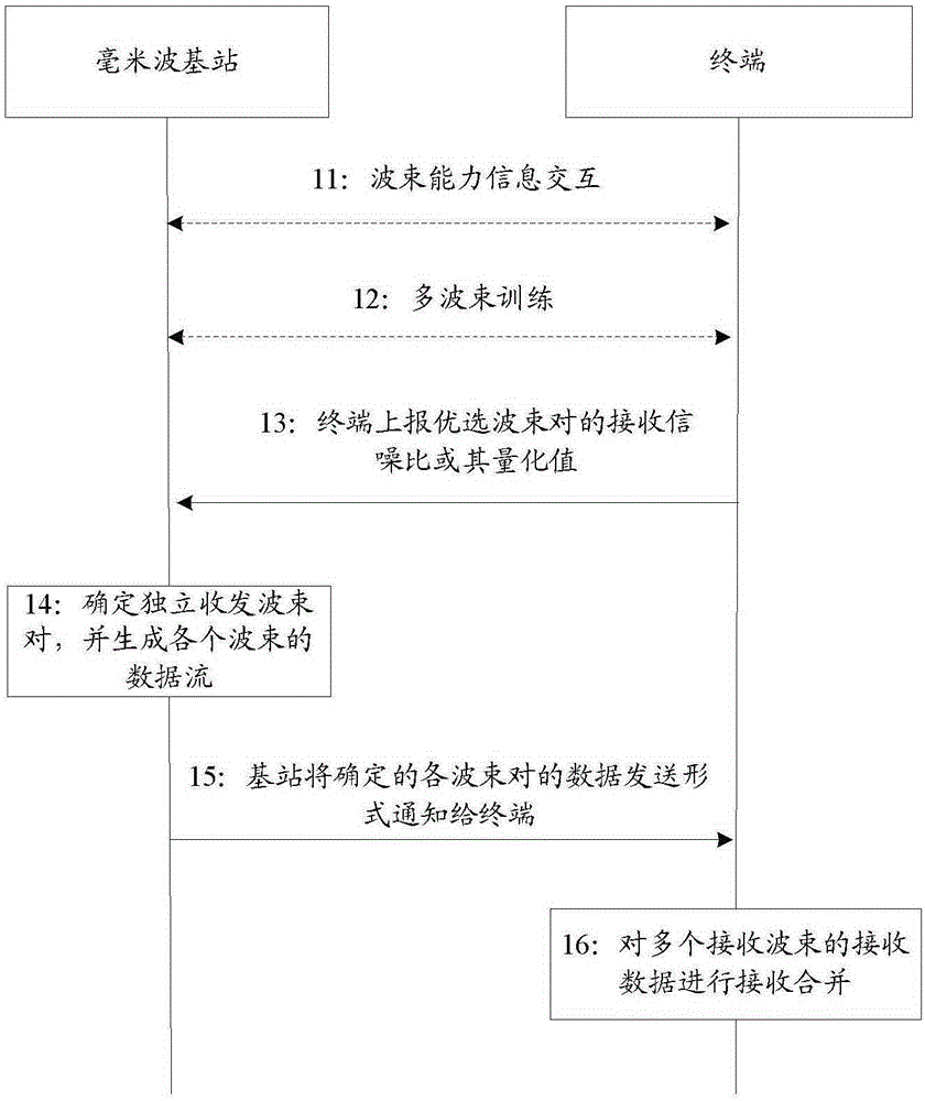
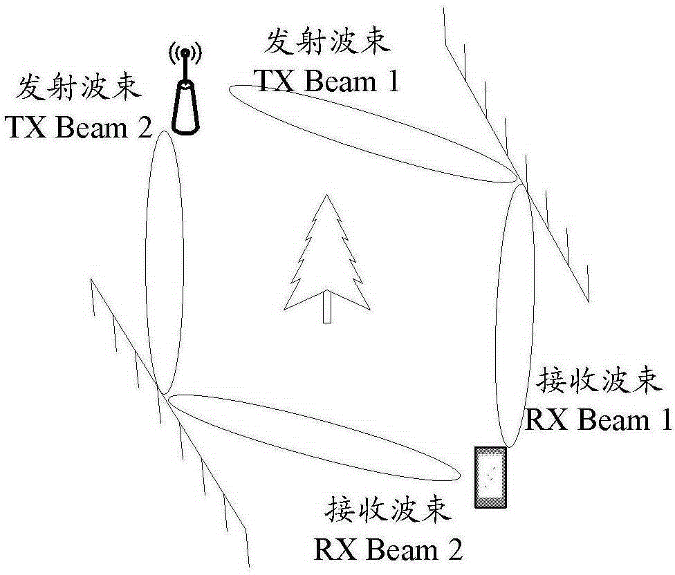
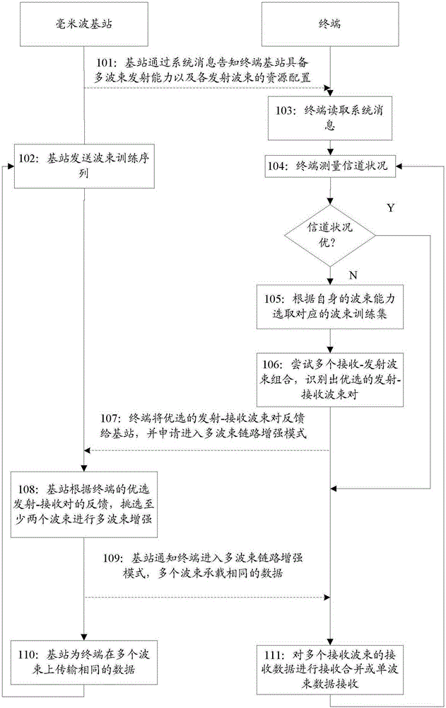
[0090] figure 2 It is a schematic diagram of the first application scenario of the embodiment of the present invention. like figure 2 As shown, the line-of-sight (LOS, Line-of-Sight) path between the base station and the terminal is blocked by objects, there is a good-quality reflection path between the terminal and the base station, and the terminal has multi-beam receiving capability (such as figure 2 As shown, including receiving beam (RXBeam) 1, receiving beam 2). image 3 It is a flow chart of Embodiment 1 of the present invention. In this embodiment, the terminal identifies two independent transceiver beam pairs with high quality based on the combining of the transmitting and receiving beams, and the terminal feeds back to the base station (such as a millimeter wave base station) to apply for multi-beam link enhancement. like image 3 As shown, the specific description of this embodiment is as follows:

[0091] Step 101: the base station sends a system message to...

Embodiment 2

[0107] figure 2 It is a schematic diagram of the first application scenario of the embodiment of the present invention. like figure 2 As shown, the LOS path between the base station and the terminal is blocked by an object, and there is a good-quality reflection path between the terminal and the base station, and the terminal has multi-beam receiving capability. Figure 4 It is a flow chart of Embodiment 2 of the present invention. In this embodiment, the terminal always performs measurements based on the combination of transmitting and receiving beams and feeds back the measured values ​​to the base station. The base station (such as a millimeter wave base station) identifies at least two preferred independent transmitting and receiving beam pairs according to the scheduling resources and the feedback from the terminal. The base station notifies The terminal enters the multi-beam link enhancement mode. like Figure 4 As shown, the specific description of this embodiment...

Embodiment 3

[0125] Figure 5 It is a schematic diagram of the second application scenario of the embodiment of the present invention. like Figure 5 As shown, there is a LOS path and a non-line-of-sight (NLOS, Non Line-of-Sight) path with excellent link quality between the terminal and the base station, and the link quality difference between the LOS path and the NLOS path is large. Image 6 It is a flow chart of Embodiment 3 of the present invention. In this embodiment, the terminal tries different transmit-receive beam combinations to measure and feed back the channel conditions of the preferred link. The base station identifies at least two preferred independent transmit-receive beam pairs for link enhancement based on the terminal's feedback and scheduling resources, and the base station notifies the terminal Enter multi-beam link enhancement mode. like Image 6 As shown, the specific description of this embodiment is as follows:

[0126] Step 301: the base station sends a system...


PUM


Abstract

The invention discloses a data transmission method and system. The method includes the steps of a base station informing the beam transmitting capability of a terminal base station and obtaining the beam receiving capability of a terminal, the base station determining the independent transmission and reception beam pairs for transmitting data according to the channel state information of the different transmission and reception beam pairs reported by the terminal, and the base station transmitting data to the terminal on each of the determined independent transmission and reception pairs and informing the terminal of the data transmission form of the determined independent transmission and reception beam pairs, when the number of determined independent transmission and reception beam pairs is at least two. The data transmission method and system disclosed in the invention solve the problem that in the conventional 3GPP or 802.11 technology, data transmission can not be realized by bi-beams or multi-beams.

Description

technical field [0001] The present invention relates to a long term evolution advanced system (LTE-Advanced, Long Term Evolution Advanced System), in particular to a data transmission method and system. Background technique [0002] With the continuous advancement of radio technology, a large number of various radio services have emerged. However, the spectrum resources on which radio services rely are limited. Facing the continuous increase in people's demand for bandwidth, traditional commercial communications mainly use 300MHz to 3GHz. The spectrum resources in the space show an extremely tight situation, which can no longer meet the needs of future wireless communications. [0003] In the future wireless communication, carrier frequencies higher than those used in the fourth generation (4G) communication system will be used for communication, such as 28GHz, 45GHz, etc. This high-frequency channel has a large free propagation loss, The shortcomings of being easily absorb...

Claims


Application Information

Patent Timeline
IPC IPC(8): H04B7/06H04B7/08
CPCH04B7/0617H04B7/0626H04B7/0632H04B7/088H04B7/06H04B7/08
Inventor 刘文豪
Owner ZTE CORP
Why Eureka
Try Eureka