Combined wrench and socket device structure

A combined structure and wrench technology, which is applied in the direction of wrenches, screwdrivers, manufacturing tools, etc., can solve the problems of elastic fatigue of elastic parts 7, joints on screw parts, inconvenient use, etc.

Active Publication Date: 2017-03-08
胡厚飞
View PDF7 Cites 0 Cited by
  • Summary
  • Abstract
  • Description
  • Claims
  • Application Information

AI Technical Summary

Problems solved by technology

[0003] However, when the screw is tightened, the working direction of the ratchet wrench 1 is towards the screw, and only the elastic member 7 cannot provide a large supporting force, and it is easy to cause the ratchet wrench 1 to move downward relative to the adapter 2, resulting in The worker must move the ratchet wrench 1 to the original position again, which is inconvenient to use; moreover, the elastic member

Method used


Image

  • Combined wrench and socket device structure
  • Combined wrench and socket device structure
  • Combined wrench and socket device structure

Examples


Embodiment Construction

[0066] In order to illustrate the central idea of ​​the present invention expressed in the column of the above-mentioned summary of the invention, it is expressed in specific embodiments. Various objects in the embodiments are drawn according to proportions suitable for illustration and description, rather than according to the proportions and drawings of actual components, and are described first.

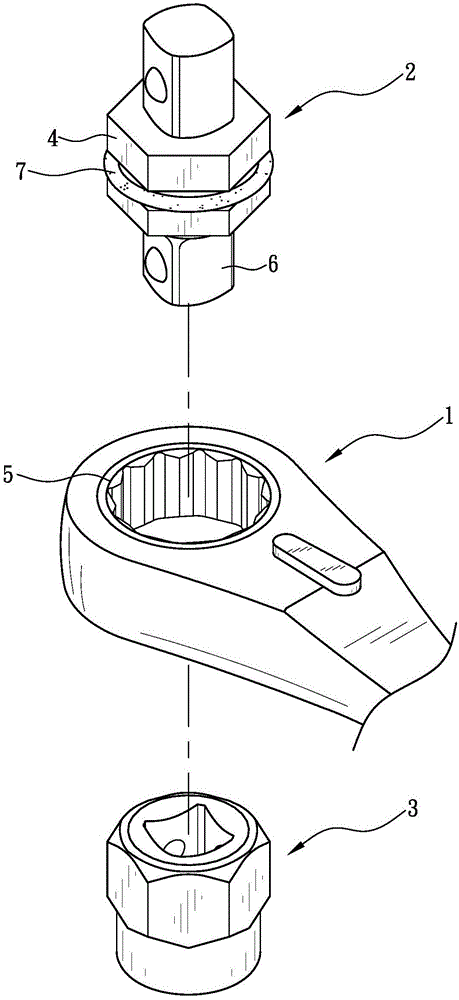
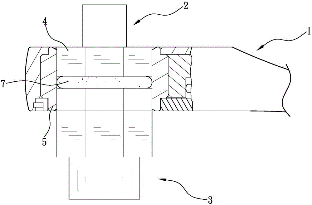
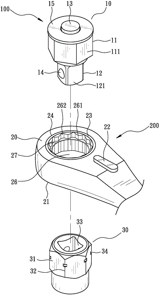
[0067] see Figure 3 to Figure 7 As shown, the combined structure of the wrench and the receiving device of the present invention includes a receiving device 100 and a wrench 200 . The receiving device 100 of the present invention includes a first receiving tool 10 and a second receiving tool 30, the first receiving tool 10 and the second receiving tool 30 can be coupled to each other, and the first receiving tool 10 can be disassembled on the wrench 200 . Wherein, the first receiving tool 10 in the present invention is an adapter, and the second receiving tool 30 is a sleeve. ...


PUM


Abstract

The invention provides a combined wrench and socket device structure, comprising: a wrench having a drive portion; a first socket tool having an axis, wherein the axis of the socket tool has an engaging portion at one end and a connection portion at the other end, the engaging portion is releasably engaged to the drive portion, the end of the engaging portion far away from the connection portion has a retaining edge; a second socket tool for being axially coupled to the connection portion and which has a noncircular outer edge; and a retaining device which, when the second socket tool is in the coupling position in the perpendicular direction around the axis, enables the outline of the engaging portion and the outline of the noncircular outer edge to incompletely overlap with each other in the axial direction, and enables the noncircular outer edge to retain the drive portion of the wrench.

Description

technical field [0001] The present invention relates to a combination structure of a wrench and a receiving device, in particular to a combination structure of a wrench and a receiving device that can be stopped by the receiving device during use to avoid moving up or down relative to the receiving device . Background technique [0002] Such as figure 1 and figure 2 As shown, it is an existing ratchet wrench and its accessories, which mainly include a ratchet wrench 1 , an adapter 2 and a sleeve 3 . The adapter 2 has a hexagonal engaging part 4, which is used to engage the ratchet ring 5 of the ratchet wrench 1, and expose the D head 6 at the lower end of the adapter 2, so as to connect the sleeve 3 to provide the ratchet wrench 1 can be used to drive screws of different sizes. Wherein, the adapter 2 is embedded with an elastic member 7 around the engaging portion 4 so as to have a stable positioning effect when combined in the ratchet ring 5 . [0003] However, when t...

Claims


Application Information

Patent Timeline
IPC IPC(8): B25B13/46B25B23/00
CPCB25B13/462B25B23/0007
Inventor 胡厚飞罗启瑞
Owner 胡厚飞
Why Eureka
Try Eureka