Overall design of tilt-rotor aircraft

An aircraft and front wing technology, applied in the directions of wings, aircraft parts, aircraft control, etc., can solve the problems of difficult flight control technology and control system design, large coupling dynamic load between rotor and wing, serious impact on aircraft stability, etc. The effect of improving gliding ability, reducing induced drag, and reducing operational complexity

Active Publication Date: 2017-05-24
BEIHANG UNIV
View PDF7 Cites 4 Cited by
  • Summary
  • Abstract
  • Description
  • Claims
  • Application Information

AI Technical Summary

Problems solved by technology

[0003] 1. Considering the actual adaptability to the site, conventional tiltrotors have a small wingspan and poor gliding performance. It is difficult to use the aircraft to glide and make an emergency landing after the engine stops in the air.
[0004] 2. The smaller wingspan makes the wing area smaller. For example, the Osprey transport aircraft (MV-22) has a wingspan of only 14 meters and a wing area of ​​28 square meters
[0006] 1. Rotors and wings shield each other to cause aerodynamic interference. For example, the interference of the wings of the Osprey transport aircraft (MV-22) causes a loss of 20%-30% of the lift in the hovering state, resulting in a much lower hovering efficiency. conv

Method used


Image

  • Overall design of tilt-rotor aircraft
  • Overall design of tilt-rotor aircraft

Examples


Embodiment Construction

[0038] The following content describes in detail the specific embodiment of the present invention in conjunction with the accompanying drawings:

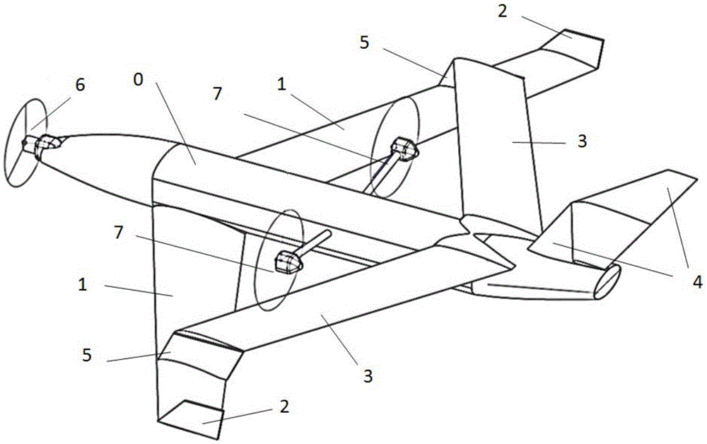
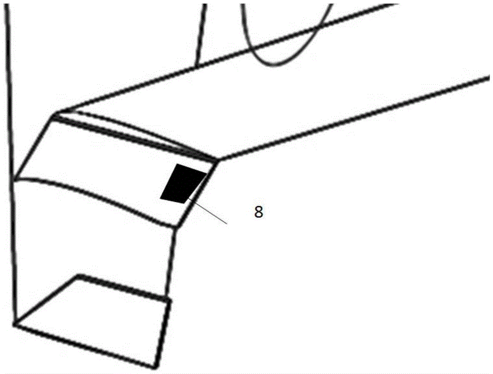
[0039] see figure 1 , figure 2 , the aircraft includes a fuselage 0, a front wing 1 and a T-tail 4, wherein the end of the front wing 1 is equipped with a winglet 2, and the connecting plate 5 is equipped with a damping plate 8, which assists the linkage of the T-tail 4 when turning The forward sweep of the rear wing 3 contains anhedral, and the angle is 1-2 degrees. Flaps (not shown in the figure) are equipped, and the connection position with the front wing 1 is 70% of the position away from the fuselage on the front wing 1. , the rear wing 3 is connected to the front wing 1 through a connecting plate 5 .

[0040] The front wing 1 is swept up and reversed, with flaps (not shown in the figure) and adjustable slats (not shown in the figure).

[0041] The front wing 1 and the rear wing 3 are combined to form a structure, and the ...


PUM


Abstract

The invention provides overall design of a tilt-rotor aircraft. According to the technical scheme, a wing arrangement structure and power distribution of the aircraft are provided. The aircraft comprises a fuselage, front wings, T-shaped emages, winglets and a rear wing. The ends of the front wings are provided with the winglets. The rear wing is connected with the main wings through a connecting plate and connected with the fuselage. The T-shaped emages are arranged on the rear portion of the whole aircraft. Three engines are further mounted and independently move. The included angles between the axial directions of the engines and the horizontal plane during vertical take-off and landing of the aircraft are 80-100 degrees. The rotating speeds and the angles of the engines are adjusted through a flight control system. The engines assist to control the posture of the aircraft. When the aircraft tilts, the engines forward rotate till the included angles between the axial directions of the engines and the horizontal plane are zero degree.

Description

technical field [0001] The invention belongs to the field of aircraft design, and in particular relates to the wing layout and power arrangement of the aircraft. Background technique [0002] Compared with conventional fixed-wing aircraft, the existing tilt-rotor aircraft has the advantages of less dependence on the runway, a longer flight distance than helicopters, and a higher maximum level flight speed. However, due to the limitations of the layout, there are still many disadvantages. From the perspective of the overall layout of the aircraft, since most conventional tiltrotors adopt a conventional layout, the following problems will arise: [0003] 1. Considering the actual adaptability to the site, conventional tiltrotors have a small wingspan and poor gliding performance. It is difficult to use the aircraft to glide and make an emergency landing after the engine stops in the air. [0004] 2. The smaller wingspan makes the wing area smaller, such as the Osprey transpor...

Claims


Application Information

Patent Timeline
IPC IPC(8): B64C3/00B64C9/14
Inventor 周尧明张佳奇赵嘉珩周舒
Owner BEIHANG UNIV
Why Eureka
Try Eureka