A blast furnace slag sensible heat recovery slag cooler

A sensible heat recovery and slag cooler technology, applied in furnaces, furnace components, waste heat treatment, etc., can solve the problems of low waste heat utilization efficiency, large pollutant emissions, and large equipment footprint, and improve heat recovery efficiency. , The effect of high heat exchange efficiency and small footprint

Active Publication Date: 2018-12-04
TONGJI UNIV
View PDF5 Cites 0 Cited by
  • Summary
  • Abstract
  • Description
  • Claims
  • Application Information

AI Technical Summary

Problems solved by technology

[0004] The purpose of the present invention is to overcome the problems of high energy consumption, large equipment footprint, secondary energy loss, low waste heat utilization efficiency, large water consumption and large pollutant discharge in the traditional slag waste heat recovery process, and combine the heat transfer mechanism of solid particles , a liquid-solid heat exchange type blast furnace slag waste heat recovery device is designed, that is, multi-layer heat exchange plate bundles or tube bundles are arranged in a cylindrical box, and water is used as the heat recovery medium. The flow in the plate tube takes away the heat of the slag particles

Method used


Image

  • A blast furnace slag sensible heat recovery slag cooler
  • A blast furnace slag sensible heat recovery slag cooler
  • A blast furnace slag sensible heat recovery slag cooler

Examples


Embodiment 1

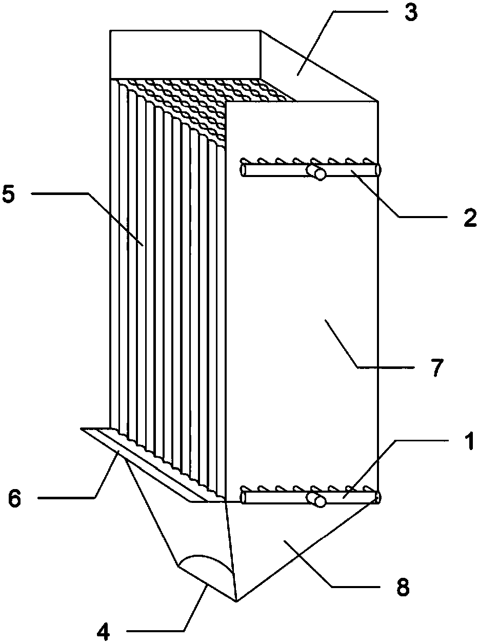
[0023] Embodiment 1: refer to figure 1 , a blast furnace slag sensible heat recovery slag cooler, comprising: cooling water inlet 1, steam outlet 2, slag inlet 3, slag outlet 4, plate and tube heat exchange core 5, louvered slag outlet baffle 6, shell and Insulation layer 7, slag outlet funnel 8.

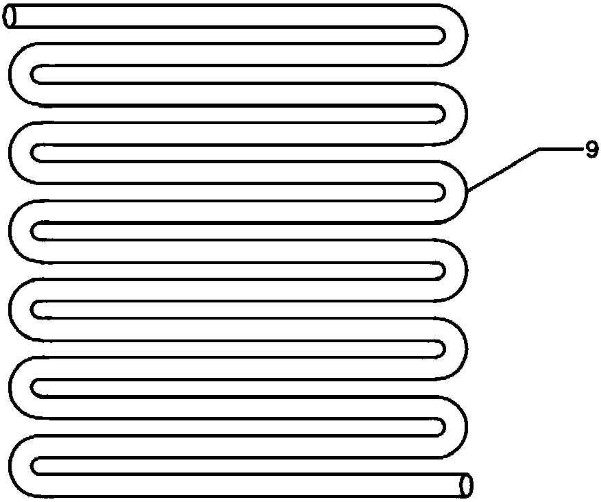
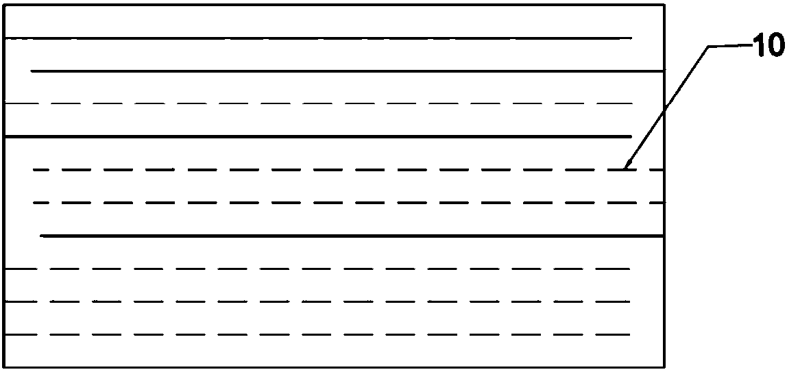
[0024] refer to figure 2 and 3 , the heat exchange core 5 of the slag cooler includes all plate and tube types, the cooling water channel is inside the plate or tube, and the high temperature slag channel is outside the plate tube.

[0025] refer to Figure 4 The louver-type slag outlet baffle 6 is a louver-type speed control device with a gear 12 that can be driven by a motor to rotate the baffle 11, and the retention of slag in the heat exchange core can be adjusted by changing the rotation range and inclination of the baffle 11 time.


PUM


Abstract

The invention relates to a blast furnace slag sensible heat recovery slag cooler which is used for furnace slag waste heat recovery, and belongs to the field of heat exchange. The blast furnace slag sensible heat recovery slag cooler comprises a plate or tube type heat exchange core, a furnace slag inlet, a louver type furnace slag outlet baffle, a furnace slag outlet hopper, a furnace slag outlet, a cooling water inlet, a steam outlet, a shell and a heat preservation layer; the heat exchange core of the blast furnace slag sensible heat recovery slag cooler is formed by stacking a plurality of plate bundles or tube bundles according to a certain manner. High-temperature furnace slag particles are poured in from the upper portion of the slag cooler, evenly flow downwards, and sweep past a heat exchange plate tube, and heat is transferred to water in the plate tube through a plate wall or tube wall. Cold water flows in a channel in the plate or tube, cross flow or adverse flow is formed between the cold water and the flowing direction of the furnace slag, and entering water is heated to form steam to be discharged out from an upper header. The cooled slag particles are discharged from an outlet in the lower portion. The flowing speed of the slag particles can be adjusted according to the louver type furnace slag outlet baffle at the lower portion of the slag cooler. The water cooling type slag cooler is simple and compact in heat exchange structure, running operation is convenient, the waste heat using efficiency is higher, and secondary losses of heat are avoided.

Description

technical field [0001] The invention belongs to the technical field of blast furnace waste heat recovery and energy-saving equipment for iron and steel enterprises, and relates to a blast furnace slag sensible heat recovery slag cooler. technical background [0002] 1. In various blast furnace slag waste heat recovery processes, air is mainly used as heat exchange medium, some directly use hot air as combustion gas, and some send hot air to waste heat boilers to generate steam for power generation. However, when air is used as the heat exchange medium, a large amount of air is required to cool each ton of slag, and the power consumption is high, and there will be a secondary loss of energy when generating hot gas, which reduces the heat utilization efficiency. [0003] 2. Iron and steel enterprises generally adopt the water quenching slag treatment process to recover the waste heat of blast furnace slag. However, this method often causes heat to be difficult to recover and d...

Claims


Application Information

Patent Timeline
Patent Type & Authority Patents(China)
IPC IPC(8): C21B3/08F27D17/00
CPCC21B3/08F27D17/004Y02P10/20Y02P10/25
Inventor 吴俐俊袁志成苑昭阔单方坚王小柳
Owner TONGJI UNIV
Why Eureka
Try Eureka