A convex-concave probe and its plasma diagnosis method

A technology of plasma and concave probe, which is applied in the field of plasma, can solve the problems of inaccurate diagnosis results, etc., and achieve the effect of accurate electron energy distribution function, elimination of space charge effect, and good quality of volt-ampere characteristic curve

Inactive Publication Date: 2018-12-21
DALIAN UNIV OF TECH
View PDF10 Cites 0 Cited by
  • Summary
  • Abstract
  • Description
  • Claims
  • Application Information

AI Technical Summary

Problems solved by technology

[0005] The present invention provides a convex-concave probe and its plasma diagnosis method to solve the problem of inaccurate diagnosis results caused by the space charge effect and probe shape and structure in the existing single-probe plasma diagnosis technology, and to obtain accurate Plasma space potential, electron density and electron energy distribution functions

Method used


Image

  • A convex-concave probe and its plasma diagnosis method
  • A convex-concave probe and its plasma diagnosis method
  • A convex-concave probe and its plasma diagnosis method

Examples


Embodiment 1

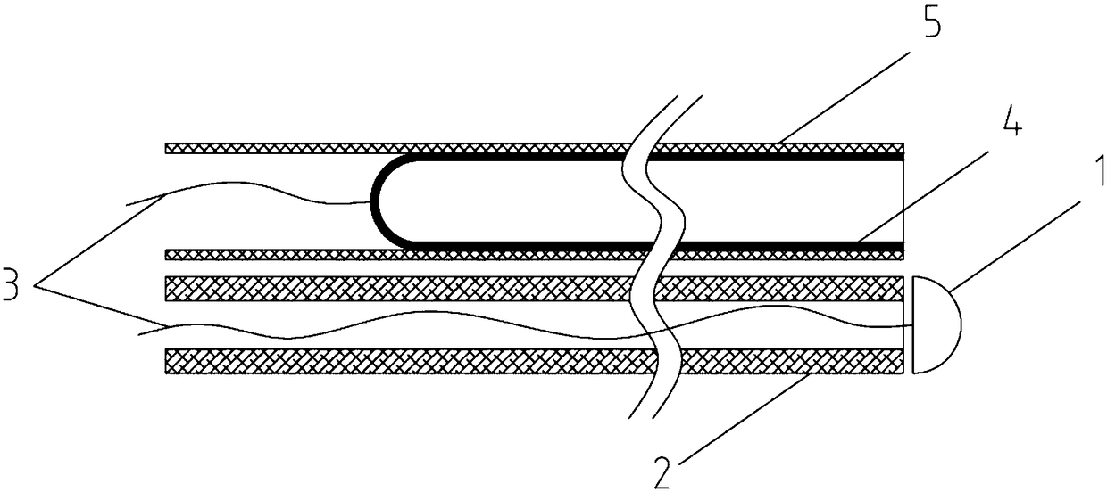
[0023] figure 1 The convex probe 1, the insulating tube 2 and the metal wire 3 form a convex probe assembly; the convex probe 1 is hemispherical and has a diameter of 2 mm; the insulating tube 2 has the same diameter as the convex probe 1; the plane part of the hemisphere of the convex probe 1 It is directly opposite to one end of the insulating tube 2, leaving a gap of 0.2mm in between; the convex probe 1 is connected to the metal wire 3 on the plane of the hemisphere, and the metal wire 3 passes through the insulating tube 2 to connect with the external circuit.

[0024] figure 1 Concave probe 4, insulating sleeve 5 and metal wire 3 form a concave probe assembly; concave probe 4 is cylindrical, with an inner diameter of 1.7mm and a depth of 30mm; one end of the cylinder of concave probe 4 is open, and the concave probe 4 cylinders are tightly sleeved with an insulating sleeve 5, and the edge of one end of the concave probe 4 cylinder is flush with the edge of the insulating...

Embodiment 2

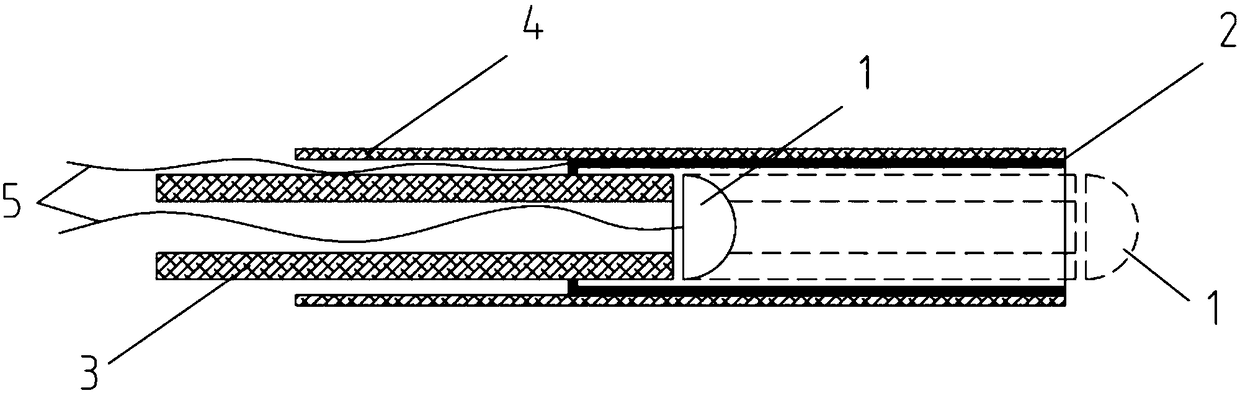
[0028] figure 2 The convex probe 1, the insulating tube 2 and the metal wire 3 form a convex probe assembly; the convex probe 1 is hemispherical, with a diameter of 1.8 mm; the insulating tube 2 is the same diameter as the convex probe 1; the plane of the hemisphere of the convex probe 1 The part is directly opposite to one end of the insulating tube 2, leaving a gap of 0.16mm between them; the convex probe 1 is connected to the metal wire 3 on the plane of the hemisphere, and the metal wire 3 passes through the insulating tube 2 to connect with the external circuit.

[0029] figure 2 The concave probe 4, the insulating sleeve 5 and the metal wire 3 form a concave probe assembly; the concave probe 4 is cylindrical, with an inner diameter of 2 mm and a depth of 30 mm; one end of the concave probe 4 cylinder is open, and the concave probe 4 An insulating sleeve 5 is tightly sleeved on the outside of the cylinder, and the edge of the open end of the concave probe 4 cylinder is...

Embodiment 3

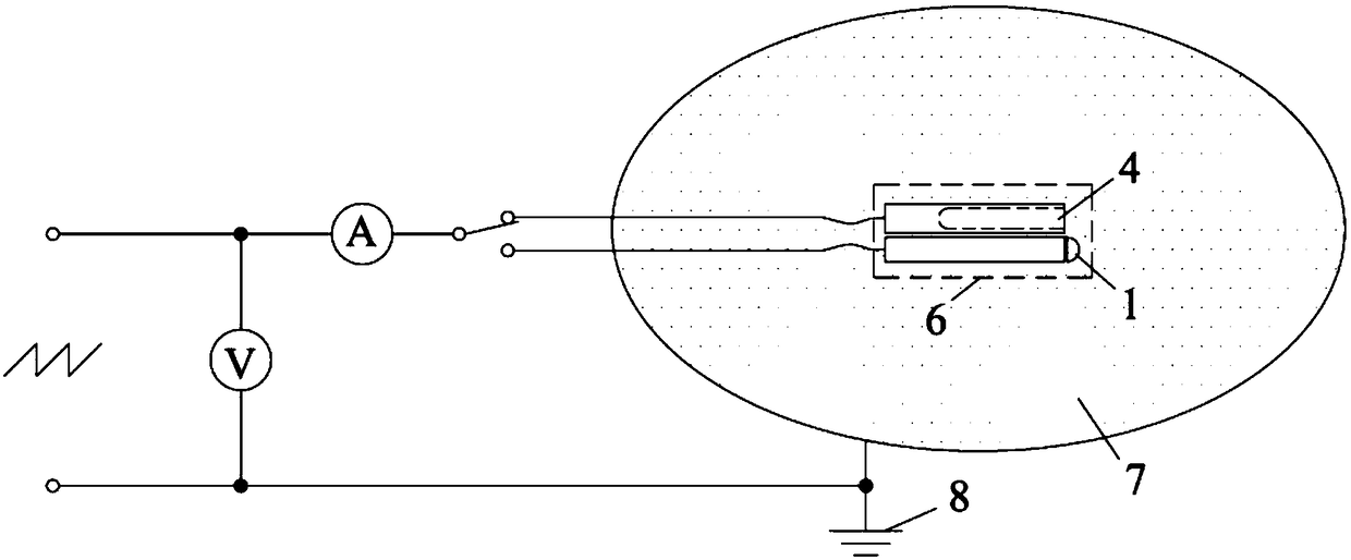
[0033] image 3 The convex probe assembly and the concave probe assembly constitute a split-type convex and concave probe assembly 6 placed in the plasma 7; at the same time, a scanning bias voltage is applied between the convex probe 1 and the concave probe 4 and the plasma ground electrode 8 , and measuring the variation of the respective currents of the convex probe 1 and the concave probe 4 with the scanning bias voltage, and obtaining the respective volt-ampere characteristic curves of the convex probe and the concave probe.


PUM


Abstract

The invention provides a convex-and-concave probe and a plasma diagnosis method thereof. The convex-and-concave probe and the plasma diagnosis method are used for diagnosing plasma for acquiring accurate plasma spatial potential, electron density and electron energy distribution function. The convex-and-concave probe is characterized in that a convex probe, an insulating tube and a metal lead form a convex probe assembly; a concave probe, an insulating sleeve tube and a metal lead form a convex probe assembly; the convex probe assembly and the concave probe assembly form a convex-and-concave probe assembly; the convex-and-concave probe assembly comprises a split type and an integral telescoping type; and in plasma diagnosis, current changes of the convex probe and the concave probe along with scanning offset voltage are measured, and volt-ampere characteristic curves of the convex probe and the concave probe are obtained, and the electron energy distribution function is obtained by means of a formula. The convex-and-concave probe and the plasma diagnosis method thereof can accurately indicate the plasma spatial potential and determine the electron collection area of the convex probe, and furthermore realize more accurate electron density and electron energy distribution function. The convex-and-concave probe and the plasma diagnosis method thereof have advantages of least interference of the convex probe to the plasma, uniform current density and higher accuracy of the obtained electron energy distribution function.

Description

technical field [0001] The invention belongs to the field of plasma technology, and relates to a convex-concave probe and a plasma diagnosis method thereof, which are used for diagnosing plasma to obtain accurate plasma space potential, electron density and electron energy distribution functions. Background technique [0002] The most commonly used technology for diagnosing plasma is the single probe, which is to place a small metal electrode, the probe, in the plasma, apply a scanning bias voltage between the probe and the plasma ground electrode, and then measure the probe The current varies with the scanning bias voltage to obtain the volt-ampere characteristic curve, and then the parameters of the plasma are obtained by analyzing the volt-ampere characteristic curve, including the plasma space potential, electron density, and electron energy distribution function. The shape of the probe is spherical, flat or cylindrical. The method of analyzing the volt-ampere characteri...

Claims


Application Information

Patent Timeline
Patent Type & Authority Patents(China)
IPC IPC(8): H05H1/00
CPCH05H1/0081
Inventor 陆文琪李建泉徐军王奇
Owner DALIAN UNIV OF TECH
Why Eureka
Try Eureka