Initial rainwater pollutant interception facility and interception operation method

A technology for initial rainwater and facilities, applied in water/sludge/sewage treatment, water/sewage treatment, chemical instruments and methods, etc., to facilitate regular cleaning and improve effluent quality

Inactive Publication Date: 2017-07-14
TIANJIN WATER RESOURCES RES INST
View PDF6 Cites 6 Cited by
  • Summary
  • Abstract
  • Description
  • Claims
  • Application Information

AI Technical Summary

Problems solved by technology

[0003] The main purpose of the present invention is to solve the problems in the above-mentioned rainwater sewage interception, and provide a kind of initial rainwater sewage interception facility and sewage interception operation method

Method used


Image

  • Initial rainwater pollutant interception facility and interception operation method
  • Initial rainwater pollutant interception facility and interception operation method

Examples


Embodiment 1

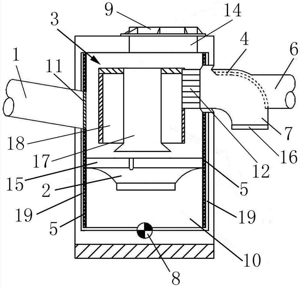
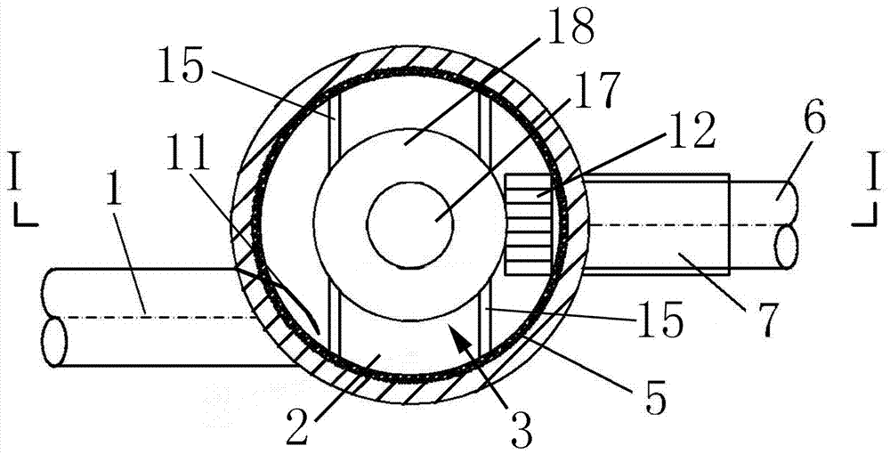
[0023]It consists of the main body of the facility (13), the water inlet pipe (1), the water outlet pipe (6), the guide tube (3), the guide plate (2), the sediment collection area (10), the water outlet collection port (12), the slag discharge The main body of the facility (13) is barrel-shaped as a whole, and the main body of the facility (13) is made of cement products, cast iron or modified plastic materials, and water inlet pipes (1) are arranged on both sides of the upper part of the main body of the facility (13). and the water outlet pipe (6), the water inlet pipe (1) and the water outlet pipe (6) are connected with the main body (13) of the facility, the water inlet pipe (1) and the water outlet pipe (6) are made of metal material or modified plastic material, and the facility The water inlet pipe (1) is installed on one side of the main body (13), and the water inlet pipe (1) is inserted into the facility main body (13) at an oblique angle, and the water inlet pipe (1)...

Embodiment 2

[0025] A support frame (15) is set in the middle of the main body (13) of the facility, and the support frame (15) is in the shape of a well as a whole, and pollutants with small particle sizes flow into the sediment collection area (10) from the collection channel (19) to the support frame (15) The guide tube (3) is installed on the top, the guide tube (3) is barrel-shaped as a whole, the guide tube (3) is made of metal material or modified plastic material, and the guide tube (3) is composed of the guide tube inner tube ( 17) and the outer tube of the guide tube (18), the outer tube of the guide tube (18) is packed in a barrel, the whole is a blind hole, the inner tube of the guide tube (17) is packed in a barrel, the whole is a through hole, and the inner tube of the guide tube (17) One end passes through the upper end of the guide tube outer cylinder (18), the other end of the guide tube inner tube (17) passes through the lower end of the guide tube outer tube (18), and the...

Embodiment 3

[0028] The other side of the main body of the facility (13) is provided with a water outlet pipe (6). The water outlet pipe (6) is a Y-shaped three-way pipe as a whole. One end of the water outlet pipe (6) is an opening, and one end of the water outlet pipe (6) is inserted into the facility. The inside of the main body (13) is connected with the diversion outer cylinder (18), and one end of the water outlet pipe (6) is installed with a water outlet (12), and the water outlet (12) is connected to the diversion outer tube in the main body (13) of the facility. The cylinders (18) are connected, the water outlet collection port (12) is connected with the diversion outer cylinder (18), the separated rainwater flows into the outlet pipe (6), the other end of the outlet pipe (6) is a double port, and the outlet pipe ( 6) Install the filter layer (4), the filter layer (4) seals a water outlet of the water outlet pipe (6), the filter layer (4) is the sewage collection area (7), and the ...


PUM


Abstract

The invention provides an initial rainwater pollutant interception facility and an interception operation method. The whole main body of the facility is in barrel shape. Two sides of the upper part of the facility main body are provided with a water inlet pipe and a water outlet pipe. The water inlet pipe is inclined and is inserted in the facility main body and is connected with a peripheral body tangent insertion inner wall of the facility main body. A supporting frame in the facility main body is provided with a diversion cylinder. Rainwater forms an eddy state between a porous inner wall main body and the diversion cylinder, to generate centrifugal force. Foreign matters in rainwater fall in a sediment collection region from a lower ventage of a guide plate, and are discharged by opening a discharge hole. Pollutants intercepted in the porous inner wall are eliminated through microbial decomposition. The facility is simple in structure, good in reliability, and simple in installation and maintenance, and improves an original initial rainwater pollutant interception device, and interception and treatment efficiency on rainwater runoff pollutants is improved. The pollutants intercepted in the porous inner wall are fully decomposed and treated by microorganism, and a filter layer in the water outlet pipe can fully filter rest pollutants. The improved facility main body still maintains to be integrated, and installation and overhaul are convenient, and just regular checking and desilting and pollution discharge are needed.

Description

technical field [0001] The invention relates to an improved initial rainwater sewage interception device, in particular to an initial rainwater sewage interception facility and a sewage interception operation method. Background technique [0002] China is one of the most water-scarce countries in the world. my country is rich in rainwater resources, and the collection and utilization of rainwater has become particularly important. Due to the serious pollution of the initial rainwater, it cannot be directly discharged into the receiving water body. At present, most of the initial rainwater interception devices can only simply intercept suspended solids, oil pollution and other pollutants in the initial rainwater, and the treatment efficiency is not high, especially for pollutants with small particle sizes, and the initial rainwater carries a large amount of air. Pollutants in and on the ground. Contents of the invention [0003] The main purpose of the present invention i...

Claims


Application Information

Patent Timeline
Patent Type & Authority Applications(China)
IPC IPC(8): E03F1/00E03F5/14
CPCE03F1/00E03F5/14E03F2201/10
Inventor 常素云占强吴涛许伟李岩
Owner TIANJIN WATER RESOURCES RES INST
Why Eureka
Try Eureka