Drawer-type switch cabinet

A switchgear and drawer technology, applied in the field of switchgear, can solve problems such as difficulty in installing drawers, and achieve the effect of increasing difficulty

Active Publication Date: 2017-08-01
京电电气有限公司
View PDF7 Cites 9 Cited by
  • Summary
  • Abstract
  • Description
  • Claims
  • Application Information

AI Technical Summary

Problems solved by technology

[0003] However, this utility model has the following problems: when the drawer is installed after the maintenance is completed, it is necessary to compress the elastic member while pushing the drawer, which makes it difficult to install the drawer

Method used


Image

  • Drawer-type switch cabinet
  • Drawer-type switch cabinet
  • Drawer-type switch cabinet

Examples


Embodiment Construction

[0034] The present invention will be described in further detail below in conjunction with the accompanying drawings.

[0035] This specific embodiment is only an explanation of the present invention, and it is not a limitation of the present invention. Those skilled in the art can make modifications to this embodiment without creative contribution as required after reading this specification, but as long as they are within the rights of the present invention All claims are protected by patent law.

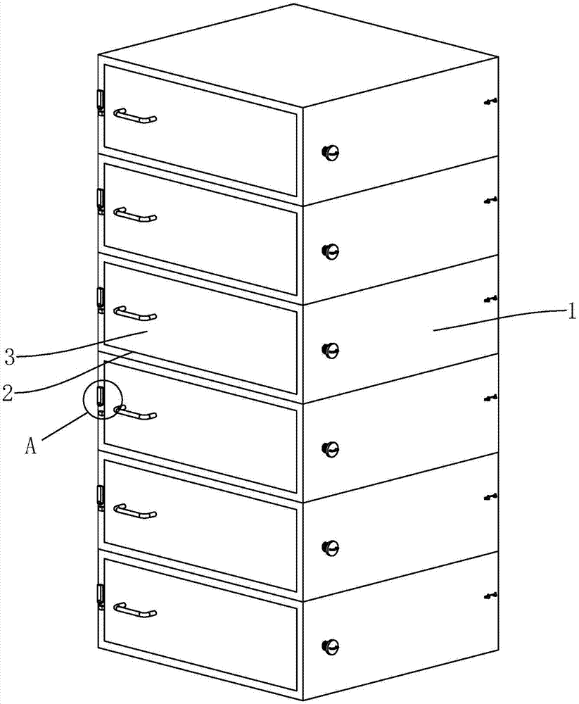
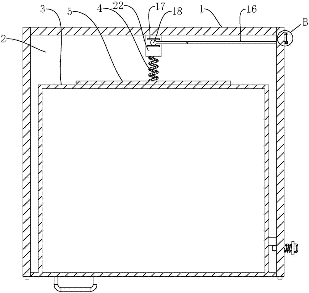
[0036] Such as figure 1 and figure 2 As shown, a drawer-type switch cabinet includes a cabinet body 1, a plurality of storage slots 2 are opened on the side of the cabinet body 1, and drawers 3 are connected to the storage slots 2 and slide horizontally. Power spring 4 is installed in placing groove 2, and power spring 4 is connected with push plate 5 to one end of placing groove 2 bottom surfaces, promotes drawer 3 by power spring 4 and makes more labor-saving when drawing out...


PUM


Abstract

The invention discloses a drawer-type switch cabinet which comprises a cabinet body, wherein a placement groove is formed in the side surface of the cabinet body; and a drawer which transversely slides is arranged in the placement groove. The switch cabinet is characterized in that a locking device for locking the drawer is arranged on the cabinet body; a power spring is arranged in the placement groove; a push plate is arranged on one side, facing towards the drawer, of the power spring; a sliding block capable of sliding in a movement direction same as that of the drawer is arranged at one end, back to the push plate, of the power spring; and a compression device for pushing the sliding block is arranged on the cabinet body. When the drawer needs to be drawn out, the locking device is opened, and then the drawer can be easily pulled out by the action of the power spring. When the drawer needs to be closed, the compression device drives the sliding block to move far away from the drawer, so that the power spring cannot obstruct the drawer when the drawer is pushed, the locking device locks a position of the drawer after the drawer is completely pushed into the placement groove, and then the compression device pushes the sliding block to move towards the drawer to compress the power spring.

Description

technical field [0001] The invention relates to a switch cabinet, in particular to a drawer type switch cabinet. Background technique [0002] The utility model patent whose authorization notification number is CN203983818U discloses a kind of drawer type switchgear. The invention cooperates with the elastic member to push the drawer outward for a certain distance to facilitate opening and pulling out of the drawer to facilitate maintenance. [0003] But this utility model has the following problems: when the drawer is installed after the maintenance is completed, it is necessary to compress the elastic member while pushing the drawer, which makes it difficult to install the drawer. Contents of the invention [0004] The purpose of the present invention is to provide a drawer type switchgear, which has the advantage that the drawer is easy to assemble and disassemble. [0005] The above-mentioned technical purpose of the present invention is achieved by the following tec...

Claims


Application Information

Patent Timeline
Patent Type & Authority Applications(China)
IPC IPC(8): H02B11/133H02B11/173
CPCH02B11/133H02B11/173
Inventor 韩军伟姚文
Owner 京电电气有限公司
Why Eureka
Try Eureka