LED lamp

A technology of LED lamps and lampshades, which is applied in the direction of lighting and heating equipment, light sources, components of lighting devices, etc. It can solve the problems that the length of lamps cannot be extended indefinitely, the cost of dealers is high, and the disassembly and assembly are inconvenient, etc., and achieve good ventilation effect , Simple structure, cost-saving effect

Inactive Publication Date: 2017-08-18
罗永强
View PDF5 Cites 2 Cited by
  • Summary
  • Abstract
  • Description
  • Claims
  • Application Information

AI Technical Summary

Problems solved by technology

[0002] The length of traditional lamps cannot be extended indefinitely, and it is inconvenient to disassemble and assemble. The cost of dealers is high, and a solid radiator is used, which makes the weight heavy and increases the cost.

Method used


Image

  • LED lamp
  • LED lamp
  • LED lamp

Examples


Embodiment 1

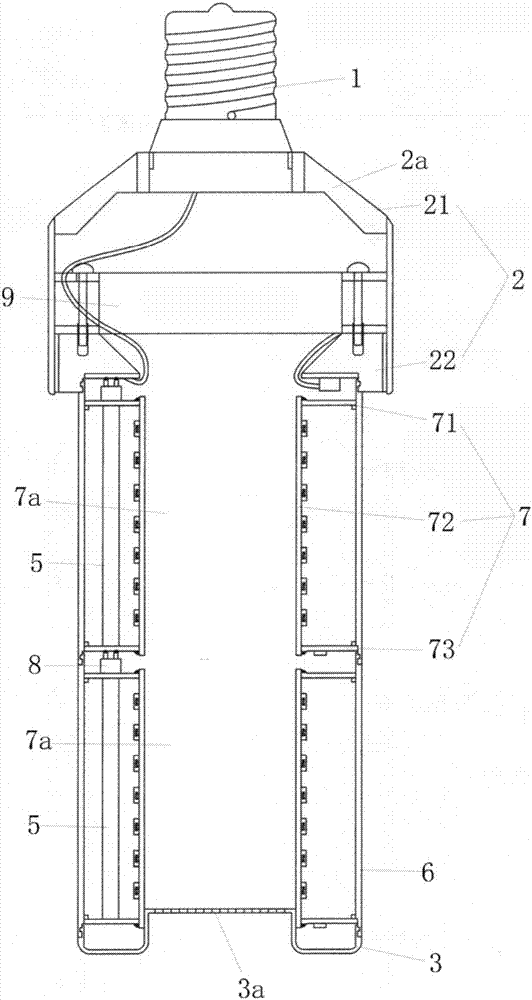
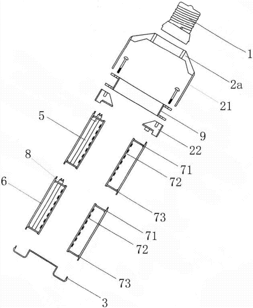
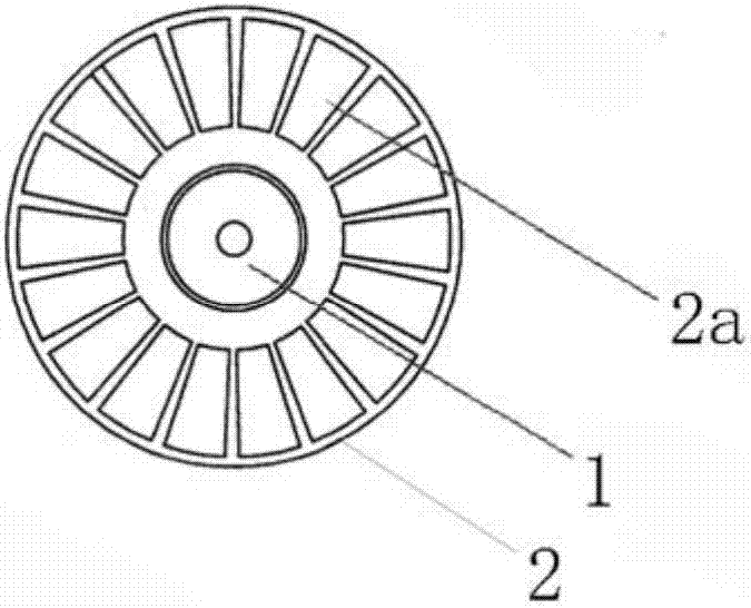
[0025] Please refer to Figure 1-7 , the LED lamp includes a lamp holder 1, a lamp holder 2, a lampshade end cover 3 and an LED lamp bead 4, the LED lamp bead 4 is electrically connected to the lamp holder through a wire 5, and the upper and lower ends of the lamp holder 2 are respectively equipped with a lamp holder 1 and a lampshade End cap 3, a lampshade tube 6 is also installed between the lamp holder 2 and the lampshade end cover 3, and a heat dissipation part 7 is arranged in the lampshade cylinder 6. Between the upper end of the lampshade cylinder 6 and the lamp holder 2, the lampshade cylinder The lower end of 6 and the end cover 3 of the lampshade are all detachable screw-in connections, and the LED lamp bead 4 is installed on the heat dissipation component 7 .

[0026] Specifically, the lampshade barrel 6 and the lampshade end cap 3 are both made of acrylic sheet, which has low cost, good light transmission effect and beautiful appearance. The screw-on connection is...

Embodiment 2

[0031] Please refer to Figure 8-10 , the difference between this embodiment and the first embodiment is only that: the lampshade cylinder 6 is three ( Figure 8 ), four ( Figure 9 ), five ( Figure 10 ) or more, the common feature of these different numbers of lampshade cylinders 6 is that every two adjacent lampshade cylinders 6 are detachably connected by a screw connection, and between the uppermost lampshade cylinder 6 and the lampshade end cover 3 It is a detachable screw connection, the lowermost lampshade tube 6 and the lampshade end cover 3 are detachable screw connection, each lampshade tube 6 is provided with a heat dissipation part 7, and the LED lamp bead 4 is installed on the On the heat dissipation component 7 in the lowermost lampshade tube 6 . A wire 5 is installed on each heat dissipation component 7 , and the wires 5 on the heat dissipation components 7 in two adjacent lampshade tubes 6 are electrically connected through the shrapnel lamp holder 8 locate...

Embodiment 3

[0033] Please refer to Figure 11 The difference between this embodiment and the above-mentioned first embodiment is only that there is one lampshade cylinder 6, and a heat dissipation component 7 is arranged inside the lampshade cylinder 6. Between the upper end of the lampshade cylinder 6 and the lamp holder 2, the lampshade cylinder 6 The lower end of the lampshade and the lampshade end cover 3 are all detachable screw-on connections, and the LED lamp bead 4 is installed on the lower aluminum substrate 73 of the heat dissipation part 7 in the lampshade tube 6 . There is only one wire 6, the upper end of which is electrically connected to the upper aluminum substrate 71, and the lower end is electrically connected to the lower aluminum substrate 73. A shrapnel lamp holder 8 is installed on the upper side of the upper aluminum substrate 71, and the shrapnel lamp holder 8 is electrically connected to the wire 6 and the lamp holder 1.

[0034] In each of the above-mentioned emb...


PUM


Abstract

The invention discloses an LED lamp which comprises a lamp cap, a lamp holder, a lampshade end cover and LED lamp beads. The lamp cap and the lampshade end cover are mounted at the upper end and the lower end of the lamp holder correspondingly. One or more lampshade barrels are further mounted between the lamp holder and the lampshade end cover. The multiple lampshade barrels are arranged in the up-and-down direction in a staggered manner. Every two adjacent lampshade barrels are connected in a detachable rotating manner. The lampshade barrel at the uppermost end and the lamp holder are connected in a detachable rotating manner. The lampshade barrel at the lowermost end and the lampshade end cover are connected in a detachable rotating manner. A heat radiation component is arranged in each lampshade barrel. The LED lamp beads are mounted on the heat radiation component in the lampshade barrel at the lowermost end. A ventilation channel in the front-and-back direction is arranged in the middle of each heat radiation component. A fan is arranged in the lamp holder. The lamp holder is provided with an air inlet. The lampshade end cover is provided with an air outlet. The air inlet communicates with the air outlet through the ventilation channels. According to the LED lamp, demounting, mounting and stocking are convenient, and the cost of dealers is reduced.

Description

technical field [0001] The invention relates to the field of LED lamps, in particular to an LED lamp. Background technique [0002] The length of traditional lamps cannot be extended indefinitely, and disassembly and assembly are inconvenient, and the cost of dealers is high, and a solid radiator is used, which is heavy and increases the cost. Contents of the invention [0003] The purpose of the present invention is to provide an LED lamp, which is convenient for disassembly and assembly, and saves the cost of dealers. [0004] In order to achieve the above object, the present invention provides an LED lamp, which includes a lamp cap, a lamp holder, a lampshade end cover and an LED lamp bead. One or more lampshade tubes are also installed between the lamp holder and the lampshade end cap. When the lampshade cylinder is one, the lampshade cylinder, the lamp holder and the lampshade end cap are all detachable screw joints. Connection; when there are multiple lampshade cyl...

Claims


Application Information

Patent Timeline
Patent Type & Authority Applications(China)
IPC IPC(8): F21K9/23F21V17/12F21V23/06F21V29/503F21V29/60F21V29/83F21Y115/10
CPCF21V17/12F21V23/06F21V29/503F21V29/60F21V29/83
Inventor 罗永强
Owner 罗永强
Why Eureka
Try Eureka