Insect trap

A technology for insect traps and insects, applied in the field of insect traps, can solve the problems of high cost, processing time, low inhalation efficiency, complicated device structure, etc., and achieves the effects of high insect inhalation efficiency, suppression of noise generation, and suppression of noise occurrence.

Active Publication Date: 2017-09-22
SEOUL VIOSYS CO LTD
View PDF11 Cites 4 Cited by
  • Summary
  • Abstract
  • Description
  • Claims
  • Application Information

AI Technical Summary

Problems solved by technology

However, as far as the chemical control method is concerned, the problem of secondary pollution is on the rise, and the biological control method or the environmental control method will require relatively more costs, processing time and effort. In terms of manufacturing methods, etc., there are problems in that the device structure is complicated, the convenience of the user is reduced, and the danger associated with the inclusion of high-voltage devices
[0006] However, with regard to the conventionally used insect traps that utilize UV ​​LEDs to capture insects with the help of suction fans, there are insects such as mosquitoes that are attached to the suction fans, and noise is generated by the fans, and the speed control of the suction fans is not suitable. The mosquitoes try to escape or are not sucked into the trap, and the airflow generated by the trap is not easy to control mechanically, the suction efficiency is low, or the problem of using too much power

Method used


Image

  • Insect trap
  • Insect trap
  • Insect trap

Examples


no. 1 example

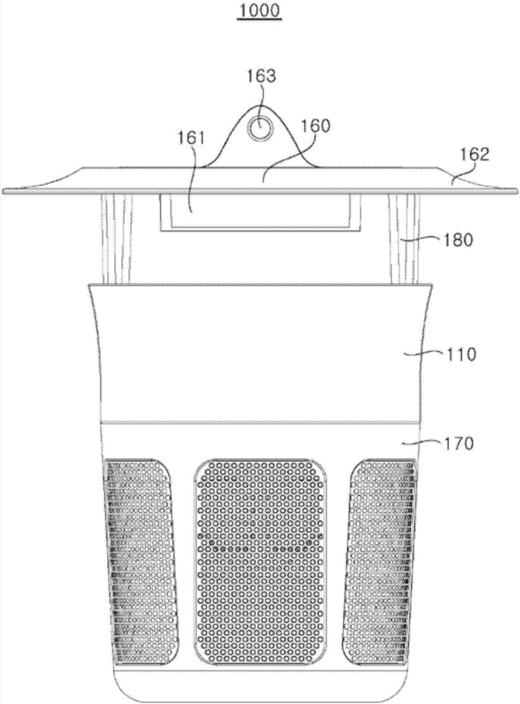
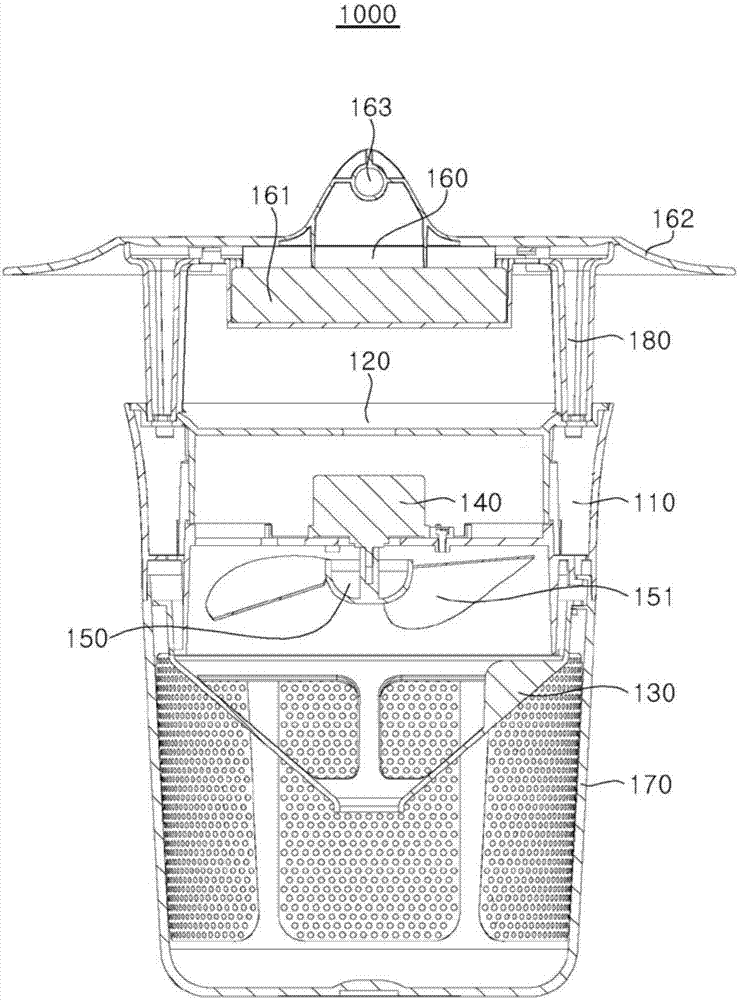
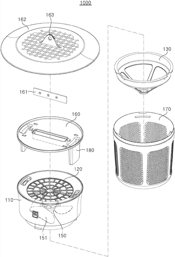
[0062] figure 1 is a side view illustrating an insect trap of one embodiment of the present invention, figure 2 is a sectional view showing an insect trap according to an embodiment of the present invention, image 3 It is an exploded perspective view illustrating an insect trap according to an embodiment of the present invention.

[0063] Refer below Figure 1 to Figure 3 , to describe in detail the components of the insect trap 1000 according to one embodiment of the present invention.

[0064] The insect trap 1000 of an embodiment of the present invention can include: a main body 110; an insect passage part 120, which can be detachably configured on the main body 110 to selectively allow insects Pass; the air dust collection part 130, which is configured at the bottom of the main body 110; the motor 140, which is located between the air dust collection part 130 and the insect passing part 120; the suction fan 150, which is located between the motor 140 and the insect pa...

no. 2 example

[0122] The second embodiment of the insect trap 2000 (not shown) of an embodiment of the present invention, compared with the first embodiment, except that the photocatalytic filter part is installed, can borrow the first embodiment As for the configuration, the configuration of the photocatalytic filter unit will be described in detail below.

[0123] The installation position of the photocatalytic filter unit is not particularly limited as long as it is a place where the UV emitted from the UV LED module 161 can be irradiated in the insect trap. Preferably, the photocatalytic filter part can be installed under the UV LED installation part 160 and / or the UV LED installation part canopy 162 .

[0124] It is preferable that the said photocatalyst filter part is not the form which protrudes in the said insect trap, but the form which is embedded. Specifically, when it is a side buried type that can be in contact with the airflow generated by the insect trap 1000 on the side, th...

no. 3 example

[0134] The insect trap 3000 of an embodiment of the present invention may also include an insecticidal UVLED installation part 190 equipped with an insecticidal UV LED module 191, such as Figure 16 As shown in , the wavelength of light emitted from the insecticidal UV LED module 191 may be 200nm to 300nm.

[0135] In addition to the insecticidal UV LED mounting part 190 with the insecticidal UV LED module 191 added, the third embodiment can borrow the composition of the first embodiment, so only the insecticidal UV LED module 191 is added below. The insecticidal UV LED mounting part 190 of the insecticidal UV LED module 191 will be described in detail.

[0136] The mounting position of the insecticidal UV LED mounting part 190 is not particularly limited, and it is preferably attached to the capturing part 170 where the captured insect stays for the longest time.

[0137]That is, in addition to the method of drying and killing insects captured in the capturing part 170, the ...


PUM


Abstract

The utility model relates to an insect trap, include: a main bod. Insect passing part, set up in in the main part for make the insect pass through, air collection dirt portion, set up in the lower part of main part, inhale the fan, be located insect passing part with between the air collection dirt portion, the UVLED installation department, set up in insect passing part's upper portion to be provided with UV LED module, seizure portion, set up in the lower part of air collection dirt portion for catch the insect, wherein, the insect passing part include: a plurality of insect clearing holes can make insect optionally pass through. The utility model relates to a insect trap not only utilizes the ultraviolet ray to lure the insect, the temperature condition liked for the control insect moreover and produce heat or produce carbon dioxide to can further improve and lure the effect.

Description

technical field [0001] The present invention relates to an insect trap, and more specifically, to an insect trap that absorbs and catches insects attracted by light-attracting light into an airflow formed by means of a suction fan. Background technique [0002] Recently, pests are increasing due to climatic influences such as global warming and environmental protection policies, and social influences. Pests not only harm crops and livestock, but also carry pathogenic bacteria such as malaria, dengue fever, and Japanese encephalitis, which can also cause adverse effects on humans. Especially recently, due to the fearful spread of Zika virus (ZIKV) infection, research on methods related to killing mosquitoes has become more active. [0003] As for the insecticide method, in the past, the chemical control method using insecticides, the biological control method using loach, etc., the physical control method of attracting pests with mosquito lamps and carbon dioxide, etc., and ...

Claims


Application Information

Patent Timeline
Patent Type & Authority Applications(China)
IPC IPC(8): A01M1/02A01M1/08H05B44/00
CPCA01M1/023A01M1/08A01M2200/012F21S2/00F21V1/00F21V7/22H05B47/10H05B45/00
Inventor 严勋植
Owner SEOUL VIOSYS CO LTD
Why Eureka
Try Eureka