Yarn impurity removing device in warp guide device of warp knitting machine

A warp knitting machine and yarn technology, used in warp knitting, textiles, papermaking, knitting, etc., can solve the problem of yarn intermingling, affecting the normal knitting, etc., and achieve the effect of reducing the probability of breakage

Active Publication Date: 2018-01-09
海宁市成达经编股份有限公司
View PDF5 Cites 1 Cited by
  • Summary
  • Abstract
  • Description
  • Claims
  • Application Information

AI Technical Summary

Problems solved by technology

However, there is a problem with the above method: since the direction of the wind force on the yarn is not

Method used


Image

  • Yarn impurity removing device in warp guide device of warp knitting machine
  • Yarn impurity removing device in warp guide device of warp knitting machine
  • Yarn impurity removing device in warp guide device of warp knitting machine

Examples


Example Embodiment

[0029] Example one

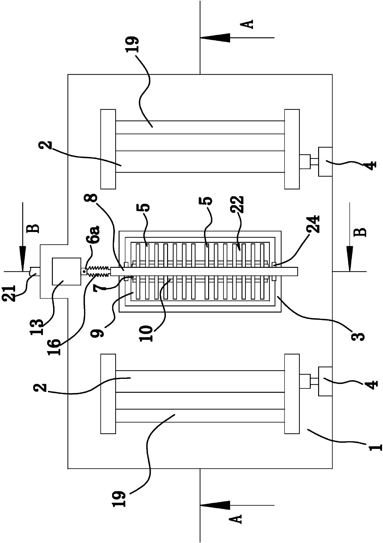
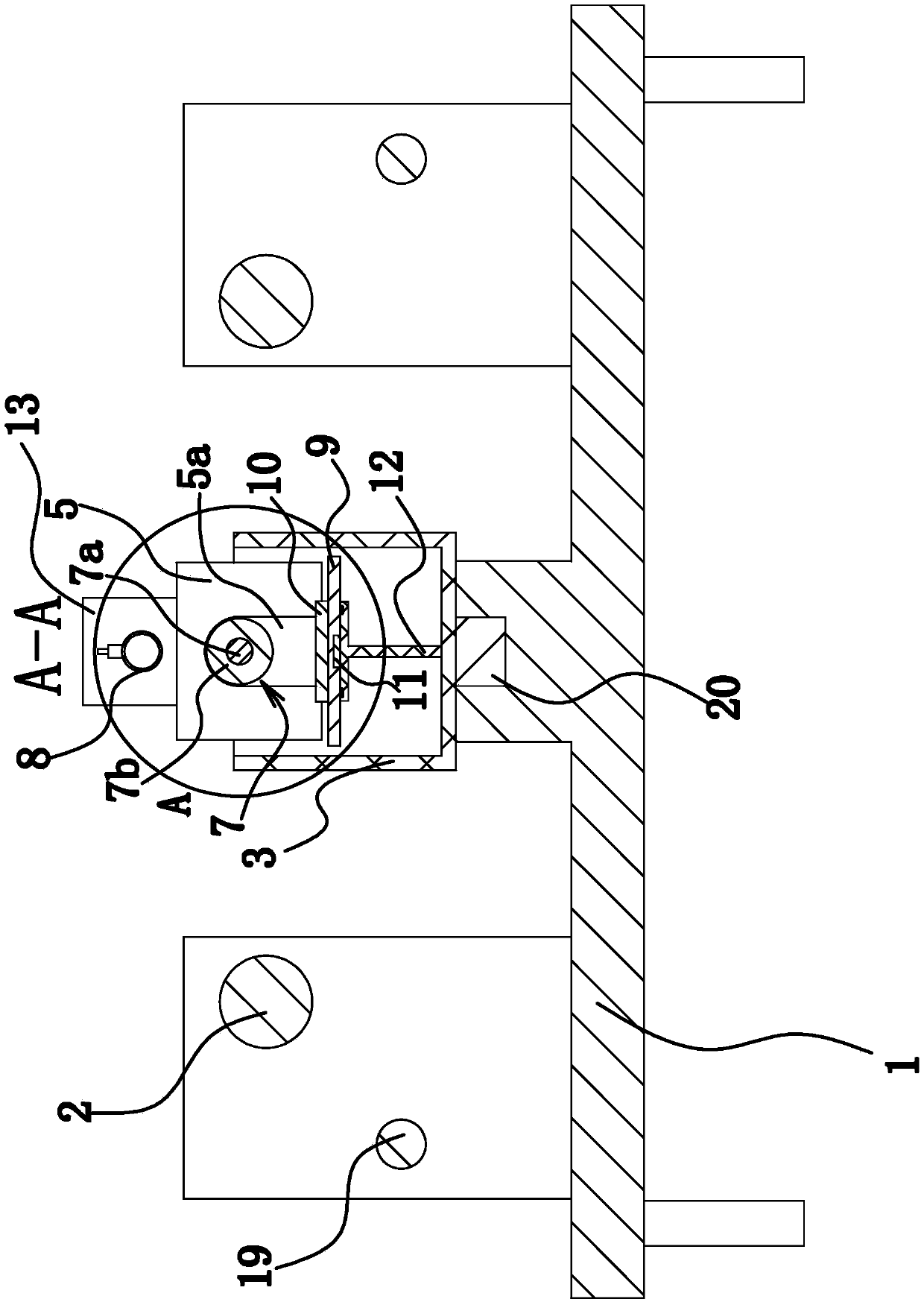
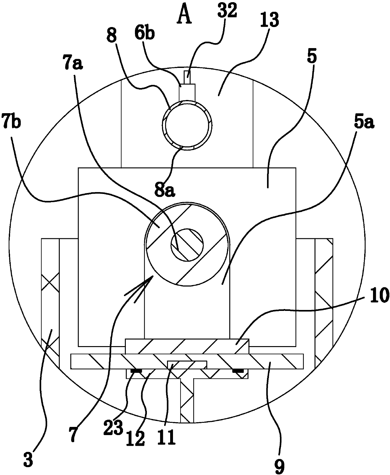
[0030] Such as Figure 1 to Figure 7 As shown, the warp guiding device of this warp knitting machine consists of frame 1, wire feed roller 2, trough body 3, motor 4, partition 5, fan 6, lubrication shaft 7, air pipe 8, support plate 9, mounting plate 10, magnetic It consists of block 11, bracket 12, muffler box 13, spring one 14, spring two 15, stainless steel bellows 16, regulating tube 17, connecting column 18 and so on.

[0031] Among them, the wire feeding roller 2 is arranged on the frame 1 along the horizontal direction, and there are two wire feeding rollers 2 and they are arranged side by side. in figure 1 Among them, the axis of the wire feeding roller 2 is arranged in the front and rear direction, and the two wire feeding rollers 2 are distributed in the left and right direction. The two wire feeding rollers 2 are both rotatably connected with the frame 1, so that the wire feeding roller 2 can rotate around its own axis. The front sides of the two w...

Example Embodiment

[0055] Example two

[0056] The second embodiment is basically the same in structure and principle as the first embodiment. The difference is that the detachable locking mechanism includes a bolt hole penetrating through the side wall of the adjusting tube 17, and a bolt provided on the side wall of the connecting column 18 The third hole and the second bolt screwed in the second bolt hole. There are multiple bolt holes three distributed along the axial direction of the connecting column 18, and the end of the second bolt is screwed into one of the third bolt holes.


PUM


Abstract

The invention provides a yarn impurity removing device in a warp guide device of a warp knitting machine, and belongs to the technical field of machines. The warp guide device of the warp knitting machine comprises a machine frame and a tank arranged on the machine frame, wherein a lubricating shaft is rotationally arranged in the tank. The yarn impurity removing device comprises an air pipe arranged above the tank, and the axial direction of the air pipe is consistent with the axial direction of the lubricating shaft; the two ends of the air pipe are a closed end and an opened end respectively, a plurality of exhaust holes are formed in the lower side of the air pipe in a penetrating mode, and the exhaust holes are aligned with the lubrication shaft; a fan is further fixedly arranged on the machine frame, the fan comprises a straight tubular air outlet part, and a stainless steel corrugated pipe making the opened end and the air outlet part communicated is arranged between the openedend and the air outlet part; an adjusting pipe and a connecting column are vertically arranged on the lower portion of the closed end, and the lower end of the adjusting pipe is fixedly connected withthe machine frame; the upper end of the connecting column is fixedly connected with the closed end, the lower end of the connecting column is inserted into the adjusting pipe, and a detachable locking mechanism for fixing the connecting column and the adjusting pipe together is arranged between the connecting column and the adjusting pipe. The yarn impurity removing device has the advantage thatyarn crossing can be prevented.

Description

technical field [0001] The invention belongs to the technical field of machinery, and relates to a warp guiding device of a warp knitting machine, in particular to a yarn impurity removing device in the warp guiding device of a warp knitting machine. Background technique [0002] The warp knitting machine is mainly composed of a knitting mechanism, a bar traversing mechanism, a warp guiding mechanism, a pulling and coiling mechanism and a transmission mechanism. The warp knitting machine has wide adaptability to raw materials and fabric varieties, and the machine productivity is high, so it develops rapidly. [0003] In yarn products, some impurities such as dust and wool are often attached to it, which affects the weaving quality. For the above-mentioned problems, the existing method is to remove the impurities attached to the yarn by blowing with a blower during the yarn conveying process. But there is a problem in the above-mentioned method: because the direction of the...

Claims


Application Information

Patent Timeline
IPC IPC(8): D04B27/02D04B35/24D04B35/32
Inventor 张波
Owner 海宁市成达经编股份有限公司
Why Eureka
Try Eureka