Public electronic equipment charging device

A technology for electronic equipment and charging devices, which is applied to battery circuit devices, circuit devices, charging stations for charging mobile devices, etc., which can solve the problems of mobile phone user identification and the need for people to guard, so as to save equipment costs and improve flexibility and convenience, the effect of improving the utilization rate

Inactive Publication Date: 2018-02-02
CHENGDU EXPERT OF BATTERY DESIGN TECH CO LTD
View PDF3 Cites 1 Cited by
  • Summary
  • Abstract
  • Description
  • Claims
  • Application Information

AI Technical Summary

Problems solved by technology

[0004] The purpose of the present invention is to provide a charging device for public electronic equipment in view of the above existing problems, which solves the problem of charging mobile phones or other electronic equipment when people go out, and solves the problem that people need to be guarded when charging electronic equipment. The problem of centralized management of electronic equipment charging solves the problem of intelligent access to electronic equipment; solves the problem of identification of mobile phone users when charging

Method used


Image

  • Public electronic equipment charging device
  • Public electronic equipment charging device
  • Public electronic equipment charging device

Examples


Embodiment 1

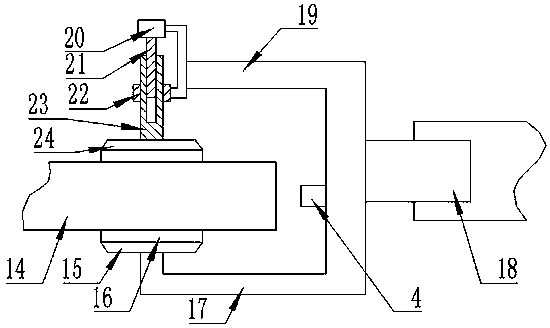
[0031] On the basis of the above embodiments, the present invention also discloses a preferred solution of a charging device for public electronic equipment. The clamping mechanism includes a lower fixed arm 17 and an upper fixed arm 19; the upper fixed arm 19 is provided with a guide ring 22 , the guide ring 22 is sleeved with a fixed rod 23, the fixed rod 23 can do linear movement in the guide ring 22, there is no relative rotation between the fixed rod 23 and the guide ring 22, the fixed rod 23 is connected with an upper part for fixing the electronic equipment The fixed claw 24 ; the lower fixed claw 15 opposite to the upper fixed claw 24 is provided on the lower fixed arm 17 .

[0032] Further, the upper fixed arm 19 is provided with a clamping motor 20, the rotating shaft of the clamping motor 20 is connected with a transmission rod 21, and the transmission rod 21 is an externally threaded rod; the fixed rod 23 has a threaded hole, and the transmission rod 21 It is conne...

Embodiment 2

[0039] On the basis of Embodiment 1, further, the control circuit includes a central control unit and a motor drive circuit. The central control unit is connected to the charging button 5, the barcode printer 6, and the barcode scanner 7 through a copper wire interface. The central control unit The motor driving circuit is connected with the central control unit signal; the pressure detection device is connected with the central control unit signal through the cable.

[0040] When the equipment is working, the charging button 5, the pressure detection device, and the barcode scanner 7 transmit the information to the central control unit through the communication interface. After processing, the central control unit transmits the information to the barcode printer 6, the fixed axis motor 12 and the clip Tight motor 20; Printer 6 prints out the bar code that needs and is used as the certificate of getting electronic equipment.

Embodiment 3

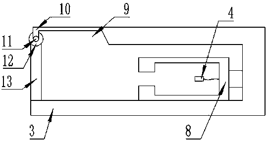
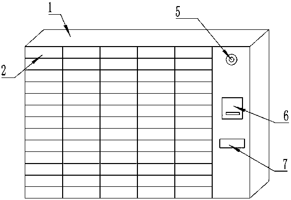
[0042] On the basis of embodiment 2, the control circuit includes a charging circuit, the charging circuit is connected to the central control unit signal through a cable, and the charging circuit is electrically connected to the charging line 4 through a cable; the interface of the charging line 4 includes a Micro USB interface, USBType C interface and Lightning interface; the charging grid 2 is matched with the housing 3, and the charging grid 2 on the charging cabinet 1 has various specifications, which can accommodate electronic devices of different sizes and structures for charging.

[0043] The charging circuit can provide electric energy for electronic devices. Micro USB interface, USB Type C interface and Lightning interface include most of the charging interface ports of electronic equipment on the market, which greatly improves the scope of services. The charging connector is replaced according to the change of the interface. Customers can basically choose the requir...


PUM


Abstract

The invention discloses a public electronic equipment charging device which comprises a charging cabinet for storing electronic equipment. The charging cabinet is provided with a plurality of charginggrids which are internally provided with accommodating housings for placing the electronic equipment. The accommodating housing is internally provided with a fixing frame which is internally providedwith a charging wire. The fixing frame comprises a clamping mechanism and a linear moving mechanism. The linear moving mechanism is arranged on the accommodating housing. A clamping mechanism is arranged on the moving part of the linear moving mechanism. The opening of the accommodating housing and the charging grid is provided with a baffle plate. The public electronic equipment charging devicecan facilitate charging of the people in a public place where charging is inconvenient, thereby realizing high convenience and high practicability. Furthermore the public electronic equipment chargingdevice has advantages of realizing centralized management in mobile phone charging, saving equipment cost, improving equipment utilization rate, realizing intelligent storing and taking of the electronic equipment, and realizing high convenience and high speed.

Description

technical field [0001] The invention relates to a charging device, in particular to a public electronic device charging device. Background technique [0002] With the popularization of electronic devices, smart phones have become an indispensable part of people's lives, but with more and more functions of smart phones and continuous enhancement of performance, the normal use time of mobile phones is getting shorter and shorter , causing the device to need to be charged frequently, but when people go shopping or playing, they often encounter the problem that the battery of the mobile phone is exhausted and cannot be used, causing great inconvenience. [0003] In the existing technology, a power bank is usually used for emergency charging, but the power bank is bulky, heavy, inconvenient to carry, and needs to be charged, which is very troublesome. Therefore, it is extremely urgent to solve the problem of charging electronic devices outdoors. Contents of the invention [0...

Claims


Application Information

Patent Timeline
Patent Type & Authority Applications(China)
IPC IPC(8): H02J7/00G07F15/00G07F17/12
CPCG07F15/006G07F17/12H02J7/0027H02J7/0042H02J7/0045Y02T90/12
Inventor 代炎利刘旭芝邓佳
Owner CHENGDU EXPERT OF BATTERY DESIGN TECH CO LTD
Why Eureka
Try Eureka