Post-grouting cast-in-place thin-wall pipe pile with grouting pipeline being reserved and construction method

A technology of thin-walled pipe piles and grouting pipes, applied in sheet pile walls, foundation structure engineering, construction, etc., can solve the problems of weakening pile end resistance, weakening pile side resistance, and affecting bearing capacity, so as to improve pile end resistance , improve the carrying capacity, and facilitate popularization and promotion

Pending Publication Date: 2018-03-13
ZHEJIANG UNIV CITY COLLEGE
View PDF10 Cites 4 Cited by
  • Summary
  • Abstract
  • Description
  • Claims
  • Application Information

AI Technical Summary

Problems solved by technology

Thin-walled tubular piles have the problem that the pile bottom sediment weakens the pile tip resistance and the pile side mud skin weakens the pile side resistance, which affects the bearing capacity. In addition, there are problems such as improper construction, necking and broken piles.

Method used


Image

  • Post-grouting cast-in-place thin-wall pipe pile with grouting pipeline being reserved and construction method
  • Post-grouting cast-in-place thin-wall pipe pile with grouting pipeline being reserved and construction method
  • Post-grouting cast-in-place thin-wall pipe pile with grouting pipeline being reserved and construction method

Examples


Embodiment Construction

[0031] The present invention will be further described below in conjunction with the examples. The description of the following examples is provided only to aid the understanding of the present invention. It should be pointed out that for those skilled in the art, without departing from the principle of the present invention, some improvements and modifications can be made to the present invention, and these improvements and modifications also fall within the protection scope of the claims of the present invention.

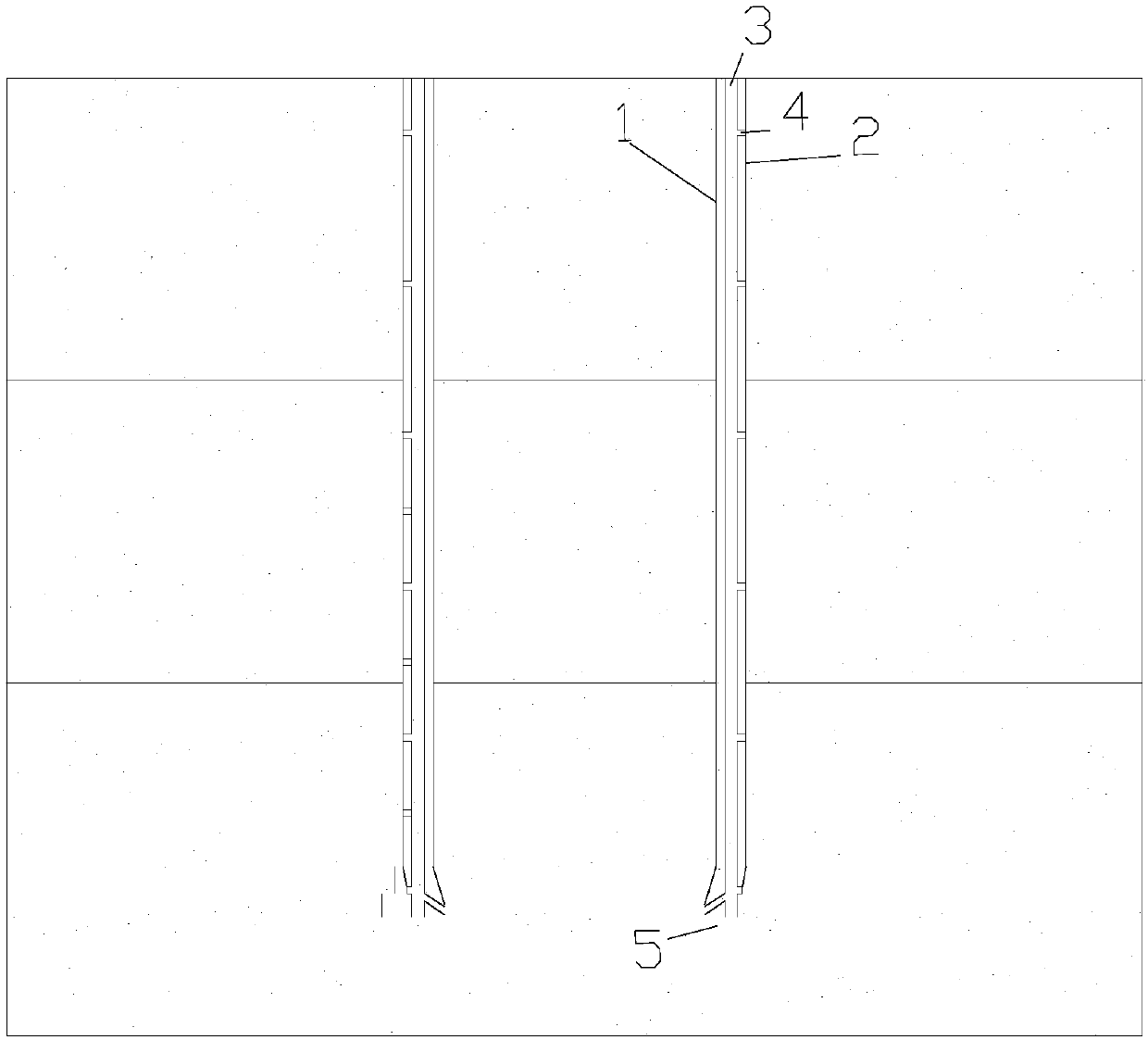
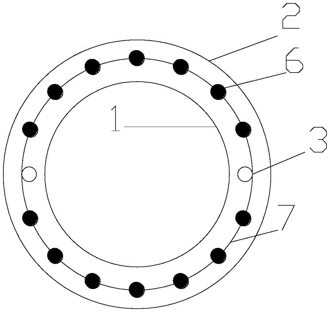
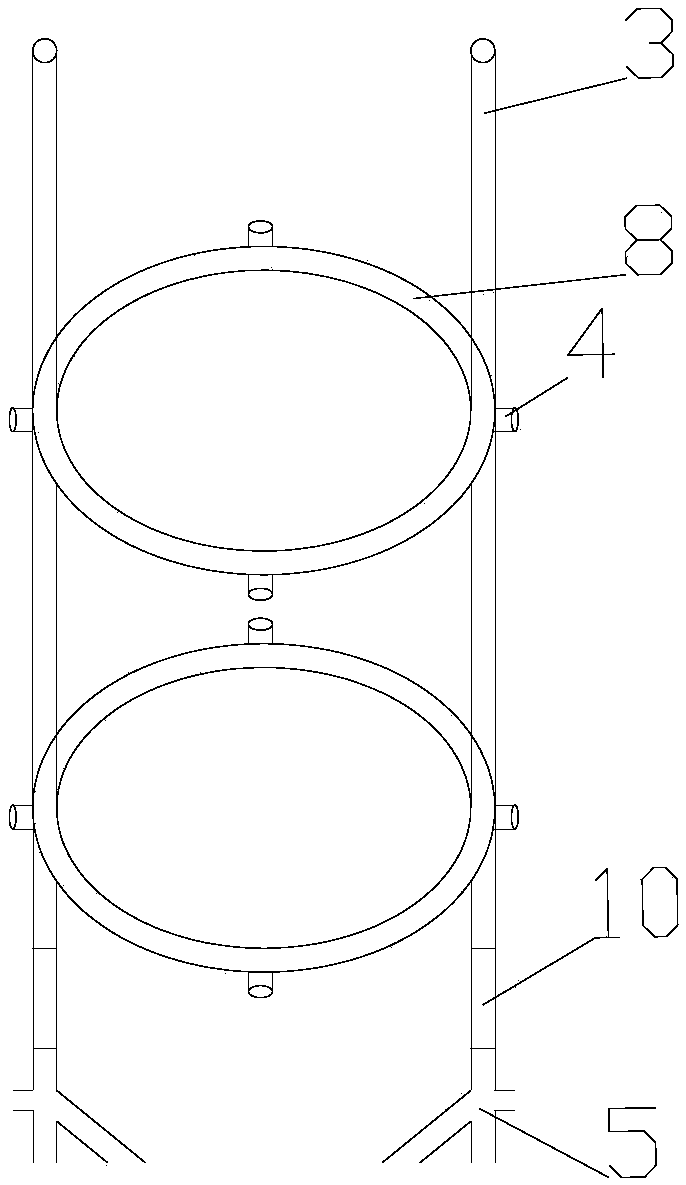
[0032] Such as Figure 1 to Figure 4 As shown, the post-grouting cast-in-place thin-walled pipe pile of the reserved grouting pipeline improves the performance of the cast-in-place thin-walled pipe pile, so that it has the post-grouting function of the pile end and pile side, and increases responses such as necking, The ability to solve engineering problems such as broken piles and insufficient bearing capacity. The post-grouting cast-in-place thin-walled pipe p...


PUM


Abstract

The invention relates to a post-grouting cast-in-place thin-wall pipe pile with a grouting pipeline being reserved. The post-grouting cast-in-place thin-wall pipe pile comprises a reinforcement cage and a post-grouting device. The post-grouting device comprises grouting pipes, pile side one-way grout outlets, pile end one-way root-type grout outlets, pile side ring-type grouting pipes, grouting pipe pile side connectors and pile end grouting pipes. The grouting pipes are fixed to the two sides of the reinforcement cage. The pile side ring-type grouting pipes are fixed to the outer circle of the reinforcement cage. The pile side one-way grout outlets are distributed in the circle of each pile side ring-type grouting pipe at equal intervals. The two sides of each pile side ring-type groutingpipe are connected with the corresponding grouting pipe pile side connectors. The upper ends and the lower ends of the grouting pipe pile side connectors are connected with the grouting pipes. The pile end grouting pipes are arranged at the bottoms of the corresponding grouting pipes. The pile end one-way root-type grout outlets are formed in the lower ends of the pile end grouting pipes. The post-grouting cast-in-place thin-wall pipe pile has the beneficial effects that by adoption of the grouting technology, hole bottom dregs can be effectively removed, and the pile end resistance of the thin-wall pipe piles is increased.

Description

technical field [0001] The invention belongs to the field of foundation treatment, in particular to a thin-walled pipe pile structure. Background technique [0002] Cast-in-place thin-walled pipe piles are a new foundation treatment method that has emerged in recent years. Its advantages are fast construction speed, low cost, and high bearing capacity. Thin-walled tubular piles have the problem that the pile bottom sediment weakens the pile tip resistance and the pile side mud skin weakens the pile side resistance, which affects the bearing capacity. In addition, there are problems such as improper construction, necking and pile breakage. [0003] To sum up, it is very important to seek a thin-walled pipe pile with good performance and the ability to deal with engineering problems. Contents of the invention [0004] The purpose of the present invention is to overcome the deficiencies in the prior art, and provide a construction method for post-grouting cast-in-place thin-...

Claims


Application Information

Patent Timeline
Patent Type & Authority Applications(China)
IPC IPC(8): E02D15/04E02D5/30E02D5/62
CPCE02D5/30E02D5/62E02D15/04
Inventor 魏纲黄文王彬朱田宇姜婉青蔡诗淇孙樵黄絮
Owner ZHEJIANG UNIV CITY COLLEGE
Why Eureka
Try Eureka