Moving target detection method and device

A technology of moving target and detection method, applied in the field of steel rolling, can solve the problems of poor wall penetration performance, low software and hardware implementation cost, high false detection rate, etc. Effect

Active Publication Date: 2018-03-20
CHENGDU UNIV OF INFORMATION TECH
View PDF5 Cites 23 Cited by
  • Summary
  • Abstract
  • Description
  • Claims
  • Application Information

AI Technical Summary

Problems solved by technology

[0002] In the prior art, wireless signals are used to realize the non-contact detection of multiple moving objects indoors, and a receiver based on OFDM (Orthogonal Frequency Division Multiplexing, Orthogonal Frequency Division Multiplexing) technology is usually used to detect the RSSI (Reference Signal Strength Indicator, reference signal strength) changes, and then determine whether there is a moving target. Since the RSSI value deviates greatly within a period of time, it is mainly affected by multiple factors such as target movement, channel fading, and occlusion, and the difference method cannot be eliminated. The random jitter of the reference signal strength RSSI cannot accurately detect whether there are multiple moving targets, so this detection method has a high false detection rate
[0003] In the prior art, active radar imaging technology can also be used to detect moving targets. The transmitter actively transmits radar signals, and the receiver detects the number of moving targets by receiving radar echoes reflected by moving objects and stationary objects. Due to the traditional The working carrier of the radar signal generally works in a dozen GHz or even tens of GHz, and the performance of penetrating walls is poor
Better wall penetration performance can be achieved by increasing the power or assembling multiple transmitting and receiving antennas, but the goal of miniaturization and low power consumption of the RF module cannot be achieved
In addition, radar signals need to be processed by a strong digital signal processor or FPGA, and the cost of hardware and software implementation is high
[0004] Therefore, there is a technical problem that the moving target detection method in the prior art cannot have both high detection accuracy and low hardware and software implementation cost.

Method used


Image

  • Moving target detection method and device
  • Moving target detection method and device
  • Moving target detection method and device

Examples


Embodiment Construction

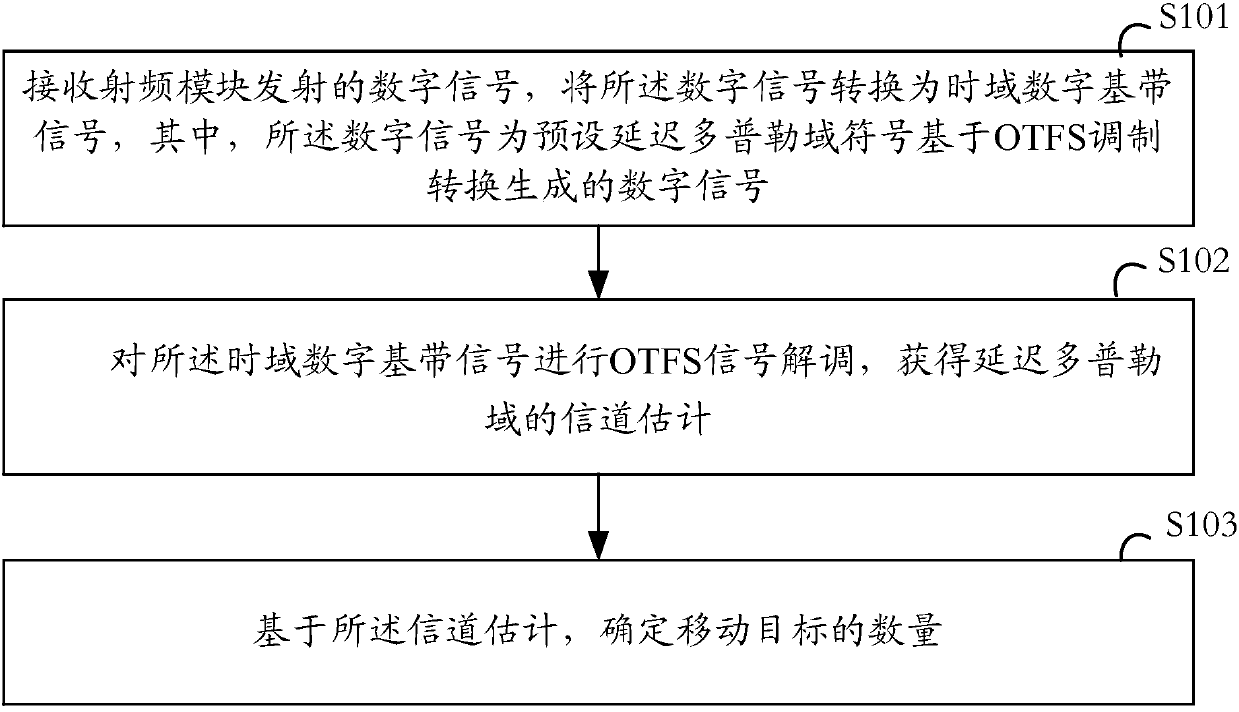
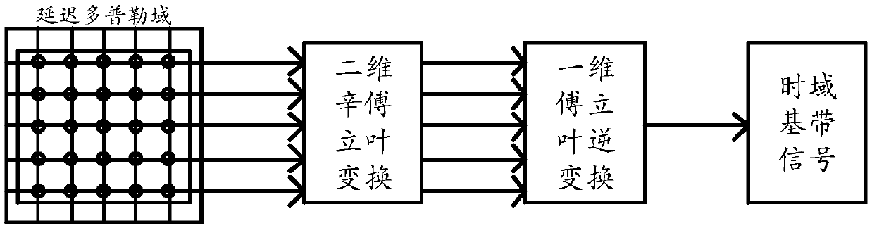
[0049] An embodiment of the present invention provides a method for detecting a moving object, which is used to improve the detection accuracy of the moving object and reduce the cost of software and hardware for detection. The method includes: receiving a digital signal transmitted by a radio frequency module, converting the digital signal into a time-domain digital baseband signal, wherein the digital signal is OTFS modulated on a preset delayed Doppler domain symbol, and then passed through a one-dimensional After the inverse Fourier transform, the signal transmitted indoors through the radio frequency module after digital-to-analog conversion; the OTFS signal demodulation is performed on the time-domain digital baseband signal to obtain a channel estimate in the delayed Doppler domain; based on the channel estimate , to determine the number of moving targets.

[0050] The technical solutions of the present invention will be described in detail below through the drawings an...


PUM


Abstract

The embodiment of the invention provides a moving target detection method and device and is used for improving detection precision of moving targets and reducing the detection software and hardware cost. The method comprises the steps of receiving a digital signal transmitted by a radio frequency module and converting the digital signal into a time domain digital baseband signal, wherein the digital signal is the signal which is transmitted to a room by the radio frequency module after OTFS (Orthogonal Time Frequency Space) modulation, one-dimensional Fourier inverse transform and digital-to-analogue conversion are carried out on a preset delay Doppler domain symbol; carrying out the OTFS modulation on the time domain digital baseband signal to obtain delay Doppler domain channel estimation; and determining the number of the moving targets based on the channel estimation.

Description

technical field [0001] The invention relates to the technical field of steel rolling, in particular to a method and device for detecting a moving target. Background technique [0002] In the prior art, wireless signals are used to realize the non-contact detection of multiple moving objects indoors, and a receiver based on OFDM (Orthogonal Frequency Division Multiplexing, Orthogonal Frequency Division Multiplexing) technology is usually used to detect the RSSI (Reference Signal Strength Indicator, reference signal strength) changes, and then determine whether there is a moving target. Since the RSSI value deviates greatly within a period of time, it is mainly affected by multiple factors such as target movement, channel fading, and occlusion, and the difference method cannot be eliminated. The random jitter of the reference signal strength RSSI cannot accurately detect whether there are multiple moving targets, so this detection method has a high false detection rate. [00...

Claims


Application Information

Patent Timeline
Patent Type & Authority Applications(China)
IPC IPC(8): H04L25/02G01S13/04
CPCG01S13/04H04L25/0222H04L25/0232
Inventor 李蠡魏华黄铫姚尧陈功凌未未杜江
Owner CHENGDU UNIV OF INFORMATION TECH
Why Eureka
Try Eureka