Wall-mounted air-conditioner indoor unit

An air conditioner indoor unit and wall-mounted technology, which is applied in the field of wall-mounted air conditioner indoor units, can solve the problems of high jet outlet structure requirements, failure to meet user requirements, troublesome installation of hanging indoor units, etc., and improve stability Sex and uniformity, uniform air flow, and the effect of improving user experience

Active Publication Date: 2018-04-13
QINGDAO HAIER AIR CONDITIONER GENERAL CORP LTD
View PDF4 Cites 2 Cited by
  • Summary
  • Abstract
  • Description
  • Claims
  • Application Information

AI Technical Summary

Problems solved by technology

[0002] Air conditioners are one of the necessary household appliances. As users have higher and higher requirements for comfort and health, the air supply method of traditional air conditioners is to send cold air into the room, then slowly convect with the surrounding air, and the heat exchange speed It is slow and cannot give people a feeling of cooling quickly, and blowing the air outlet of the indoor unit directly to people will have adverse effects on the health of users, and air-conditioning problems are prone to occur.
[0003] In response to this problem, there have been indoor units with jet outlets for soft air supply in the prior art, which use smaller air outlets to drive the surrou

Method used


Image

  • Wall-mounted air-conditioner indoor unit
  • Wall-mounted air-conditioner indoor unit
  • Wall-mounted air-conditioner indoor unit

Examples


Example Embodiment

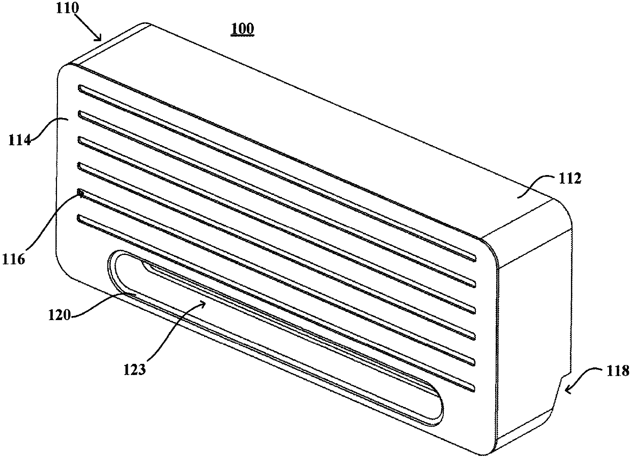
[0030] This embodiment provides a wall-mounted air conditioner indoor unit 100. For ease of description, the directions of "up", "down", "front", "rear", "top", and "bottom" mentioned in the manual are all in accordance with the wall-mounted air conditioner The spatial position relationship of the indoor unit 100 in a normal working state is limited. For example, the side of the wall-mounted air conditioner indoor unit 100 facing the user is the front, and the side close to the installation position is the rear.
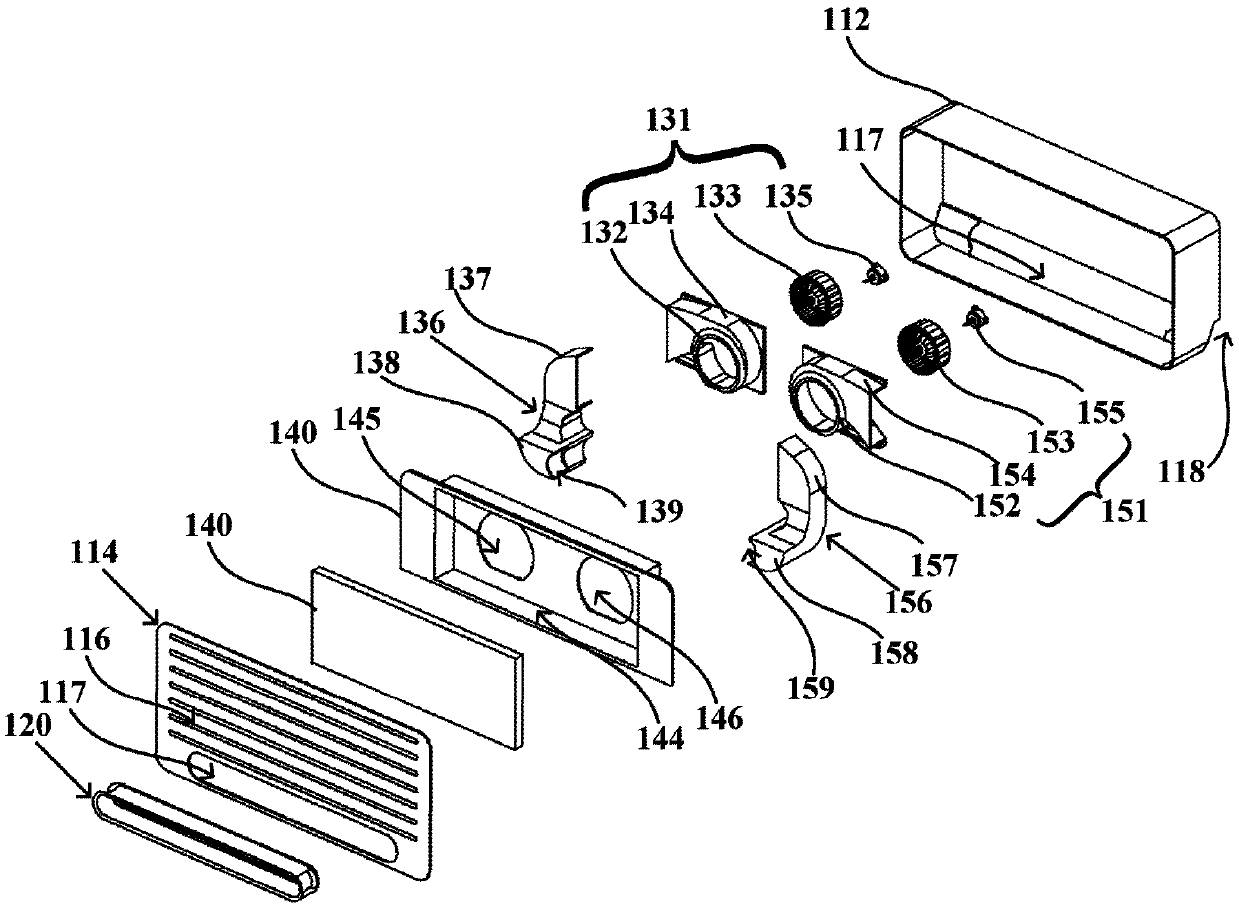
[0031] figure 1 Is a schematic external view of a wall-mounted air conditioner indoor unit 100 according to an embodiment of the present invention, and figure 2 It is a schematic exploded view of a wall-mounted air conditioner indoor unit 100 according to an embodiment of the present invention. The wall-mounted air conditioner indoor unit 100 may generally include: a housing 110, a jet component 120, a heat exchanger 140, a first air supply assembly, and a second air su...


PUM


Abstract

The invention provides a wall-mounted air-conditioner indoor unit. The wall-mounted air-conditioner indoor unit comprises a shell, a heat exchanger, an air jetting part, a first air supply assembly and a second air supply assembly. The shell is provided with an air inlet and an air supply outlet, the air supply outlet is in a long circular shape and formed in the lower portion of the shell, the air jetting part is arranged in the air supply outlet, and comprises an annular inner wall and an annular outer wall, an air draft hole is limited out by the inner side of the annular inner wall, and anair supply cavity is defined jointly by the annular outer wall and the annular inner wall; an air jetting port is formed by the edges, connected with each other, of the annular outer wall and the annular inner wall, a first air inlet and a second air inlet which are used for providing air flows which are subjected to heat exchanging through the heat exchanger for the air supply cavity are formedin the two transverse ends of the annular outer wall correspondingly, the air jetting port is used for jetting out air of the air supply cavity forwards, and therefore air in the rear of the air supply port is sucked to penetrate through the air supply port; and the first air supply assembly and the second air supply assembly are used for producing heat exchanging air flows which are subjected toheat exchanging with the heat exchanger and then supplied into the air supply cavity through the first air inlet and the second air inlet correspondingly. According to the scheme of the wall-mounted air-conditioner indoor unit, the air supply amount is increased, and the indoor temperature is integrally and evenly decreased.

Description

technical field [0001] The invention relates to an air conditioner, in particular to an indoor unit of a wall-mounted air conditioner. Background technique [0002] Air conditioners are one of the necessary household appliances. As users have higher and higher requirements for comfort and health, the air supply method of traditional air conditioners is to send cold air into the room, then slowly convect with the surrounding air, and the heat exchange speed It is slower and cannot give people a feeling of rapid cooling, and direct blowing from the air outlet of the indoor unit to people will have adverse effects on the health of users, and air-conditioning diseases are prone to occur. [0003] In response to this problem, there have been indoor units with jet outlets for soft air supply in the prior art, which use smaller air outlets to drive the surrounding air to blow out, so that the air after heat exchange is mixed with the surrounding air and sent out, but the jet outlet...

Claims


Application Information

Patent Timeline
IPC IPC(8): F24F1/00F24F13/20F24F13/30F24F13/00F24F13/08
CPCF24F1/0007F24F1/0057F24F13/00F24F13/082F24F13/20F24F13/30
Inventor 李英舒吴丽琴陈会敏王永涛
Owner QINGDAO HAIER AIR CONDITIONER GENERAL CORP LTD
Why Eureka
Try Eureka