Air intake cooling structure of new energy automobile charging pile

A new energy vehicle, air intake cooling technology, applied in electric vehicle charging technology, electrical equipment structural parts, charging stations, etc., can solve the problems of slowing down the service life of charging piles, affecting the normal use of charging piles, and injury to operators. Achieving the effect of avoiding pollution, preventing work performance, and speeding up circulation

A new energy vehicle, air intake cooling technology, applied in electric vehicle charging technology, electrical equipment structural parts, charging stations, etc., can solve the problems of slowing down the service life of charging piles, affecting the normal use of charging piles, and injury to operators. Achieving the effect of avoiding pollution, preventing work performance, and speeding up circulation

CN107911991AInactive Publication Date: 2018-04-13ANHUI POLYTECHNIC UNIV

Image

  • Air intake cooling structure of new energy automobile charging pile
  • Air intake cooling structure of new energy automobile charging pile
  • Air intake cooling structure of new energy automobile charging pile

Examples


Embodiment

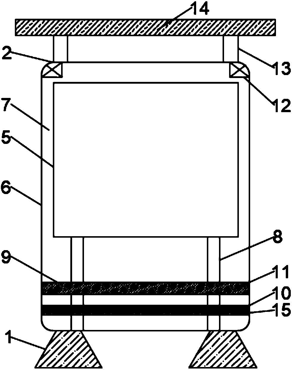
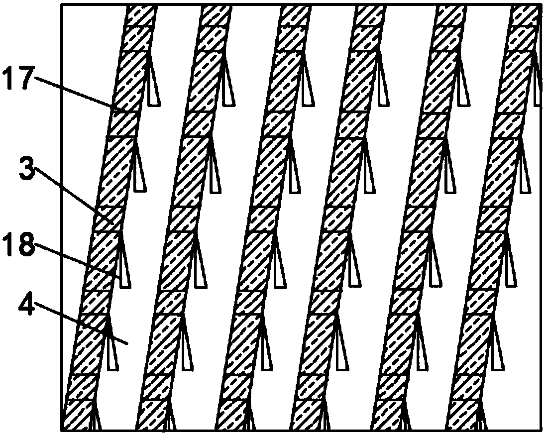
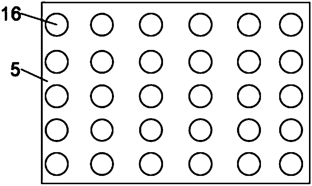
[0024] like figure 1 , figure 2 and image 3 As shown, the present invention provides an air intake cooling structure for a new energy vehicle charging pile, which includes four pillars 1, and a rectangular parallelepiped charging pile 2 is arranged on the top of the four pillars 1, and the inside of the charging pile 2 It is a hollow structure, and the bottom plate of the charging pile 2 is composed of several wind deflectors 3, and rectangular ventilation holes 4 at equal intervals are arranged between adjacent wind deflectors 3, and the charging pile 2 is Double-layer structure, the charging pile 2 includes an inner layer body 5 and an outer layer body 6, the inner layer body 5 is arranged inside the outer layer body 6, and a hollow space is arranged between the inner layer body 5 and the outer layer body 6 Interlayer 7, the inside of the outer layer body 6 is provided with a mounting rod 8, a cooling mechanism 9 and a filter layer 10, the bottom end of the mounting rod ...


PUM


Abstract

The invention discloses an air intake cooling structure of a new energy automobile charging pile, comprising four pillars. The top of four pillars is provided with a charging pile. The bottom plate ofthe charging pile is composed of a plurality of air guide plates, and rectangular ventilation holes are evenly arranged at an equal interval in the adjacent air guide plates. The charging pile comprises an inner layer body and an outer layer body. A hollow sandwich layer is arranged between the inner layer body and the outer layer body. The outer layer body is internally provided with a mountingrod, a cooling mechanism and a filter screen layer, the filter screen layer is arranged below the inner layer body, the cooling mechanism includes a wet curtain and two exhaust fans, the two exhaust fans are respectively arranged at the left and right ends of the lower surface of the top end of the inner cavity of the outer layer body, and the wet curtain is arranged above the filter screen layer.The air intake cooling structure can realize the function of air intake cooling for new energy car charging piles, the air circulation inside the charging pile and accelerate the spread of heat, thereby preventing the heat generated during the work process of a power module in the charging pile from damaging the charging pile.

Description

technical field [0001] The invention relates to the technical field of charging piles for new energy vehicles, in particular to an air intake cooling structure for charging piles for new energy vehicles. Background technique [0002] New energy vehicles refer to the use of unconventional vehicle fuels as power sources (or the use of conventional vehicle fuels, the use of new vehicle power devices), integrated vehicle power control and advanced technology in driving, the formation of advanced technical principles, with New technology and new structure cars, new energy vehicles on the existing market mostly use electric energy as the power source, and the charging pile is a terminal device used for charging new energy pure electric vehicles, and its function is similar to that in a gas station. Fuel dispenser, its user target is pure electric vehicles, and the charging pile is an outdoor device equipped to meet the charging of electric vehicles, which can be fixed in parking l...

Claims


Application Information

Patent Timeline
13 Apr 2018
Publication
CN107911991A
IPC
H05K7/20; H05K5/02; B60L11/18
CPC
B60L53/31; H05K5/0213; H05K5/0217; H05K7/20181; H05K7/20909; Y02T10/70; Y02T10/7072; Y02T90/12
Inventors
江娟娟; 许钢