Radial capillary rheometer

A capillary rheometer and capillary technology, which is applied in the field of rheology testing, can solve the problems of inconvenient observation of material flow conditions and large inlet pressure loss, and achieve the effects of improving testing efficiency, facilitating observation and saving manufacturing costs.

Active Publication Date: 2018-04-17
CHANGZHOU UNIV
View PDF14 Cites 0 Cited by
  • Summary
  • Abstract
  • Description
  • Claims
  • Application Information

AI Technical Summary

Problems solved by technology

[0002] In the structure of the traditional capillary rheometer, the capillary is generally installed under the barrel. Due to the small space where the capillary is located, the pressure sensor used for pressure measurement can only be installed on the bottom side of the barrel. When the barrel flows into the capillary, due to the stretching tendency of the polymer material, part of the pressure energy is converted into elastic energy, which makes the pressure loss at the entrance of the capillary larger, and the fluid pressure measured by the pressure sensor at the end of the barrel is higher than the pressure in the capillary. Therefore, it is necessary to perform inlet pressure correction, such as Bagley correction or double-barreled capillary (ordinary capillary and zero-length capillary) for pressure correction. At the same time, the capillary is installed directly below the barrel, and it is not convenient to observe the flow of materials in the capillary.

Method used


Image

  • Radial capillary rheometer

Examples


Embodiment Construction

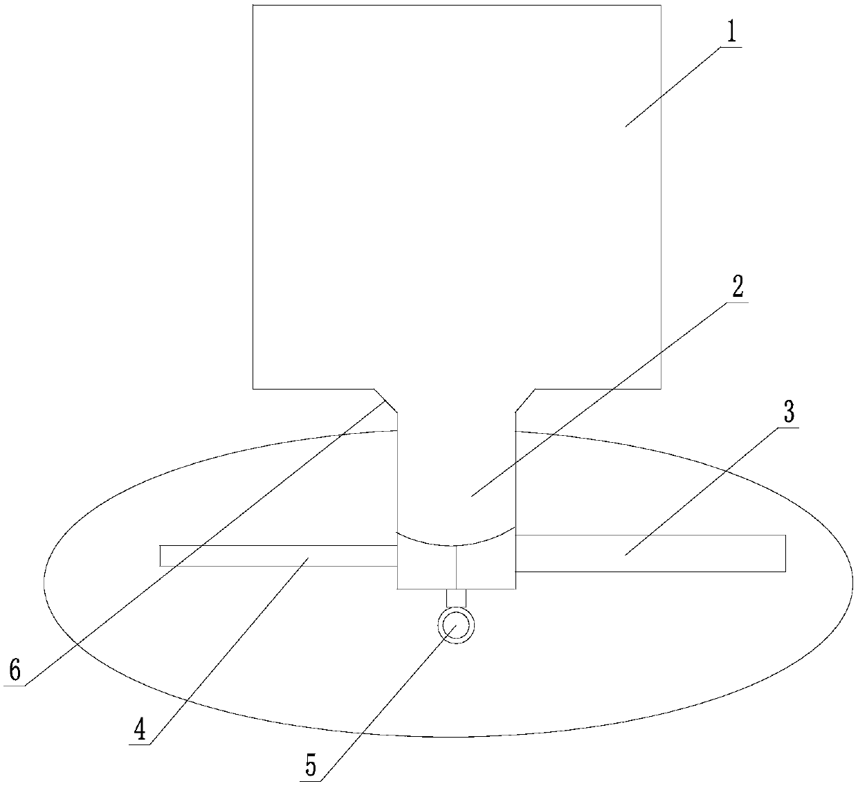
[0012] The present invention is described in further detail now in conjunction with accompanying drawing. These drawings are all simplified schematic diagrams, which only illustrate the basic structure of the present invention in a schematic manner, so they only show the configurations related to the present invention.

[0013] Such as figure 1 A radial capillary rheometer shown has a large cylinder 1 containing a polymer fluid to be tested, and a small cylinder 2 is connected to the center of the bottom of the large cylinder 1, and the diameter of the small cylinder 2 is much smaller than The diameter of the large barrel 1.

[0014] The first capillary 3 and the second capillary 4 are radially installed on both sides of the bottom end of the small barrel 2. The diameters of the first capillary 3 and the second capillary 4 can be equal or unequal, and can be selected according to needs. , Preferably, the diameters of the first capillary 3 and the second capillary 4 are betwe...


PUM

PropertyMeasurementUnit
Diameteraaaaaaaaaa

Abstract

The invention relates to a radial capillary rheometer. The radial capillary rheometer comprises a large material cylinder for containing a to-be-tested macromolecule fluid, a small material cylinder is connected with the center of the bottom of the large material cylinder, a first capillary and a second capillary are mounted on the two sides of the bottom end of the small material cylinder in a radial direction, and a pressure sensor for measuring fluid pressure is mounted on the bottom surface of the small material cylinder. The radial capillary rheometer adopts a radial arrangement of the capillary, is convenient for testing inlet pressure in the capillary, and is also convenient for observing flow condition in the capillary. Test efficiency is improved and manufacturing cost is saved.

Description

technical field [0001] The invention relates to the technical field of rheological testing, in particular to a radial capillary rheometer. Background technique [0002] In the structure of the traditional capillary rheometer, the capillary is generally installed under the barrel. Due to the small space where the capillary is located, the pressure sensor used for pressure measurement can only be installed on the bottom side of the barrel. When the barrel flows into the capillary, due to the stretching tendency of the polymer material, a part of the pressure energy is converted into elastic energy, which causes a large pressure loss at the entrance of the capillary, and the fluid pressure measured by the pressure sensor at the end of the barrel is higher than the pressure in the capillary. Therefore, inlet pressure correction is required, such as Bagley correction or double-barreled capillary (ordinary capillary and zero-length capillary) for pressure correction. At the same t...

Claims


Application Information

Patent Timeline
IPC IPC(8): G01N11/04
CPCG01N11/04
Inventor 廖华勇刘春林陶国良
Owner CHANGZHOU UNIV
Why Eureka
Try Eureka