

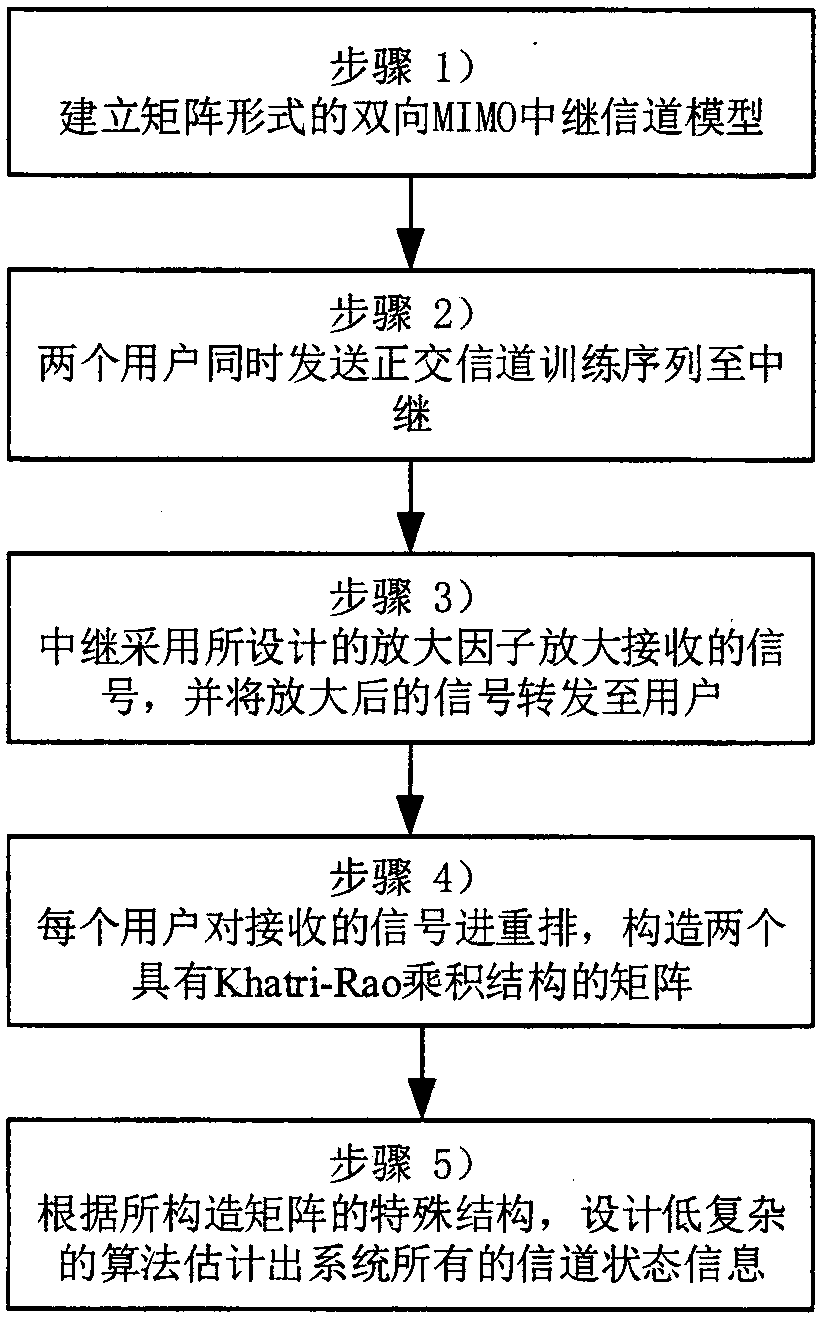
Non-iterative channel estimation method in bidirectional MIMO relay system
A channel estimation and relay system technology, applied in the field of non-iterative channel estimation, can solve the problems of high complexity and high computational complexity, and achieve the effect of reducing the burden
- Summary
- Abstract
- Description
- Claims
- Application Information
AI Technical Summary
Problems solved by technology
Method used
Image

Examples
Embodiment 1
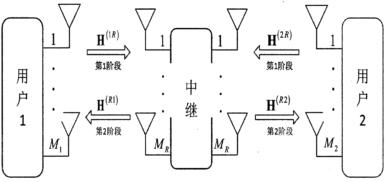
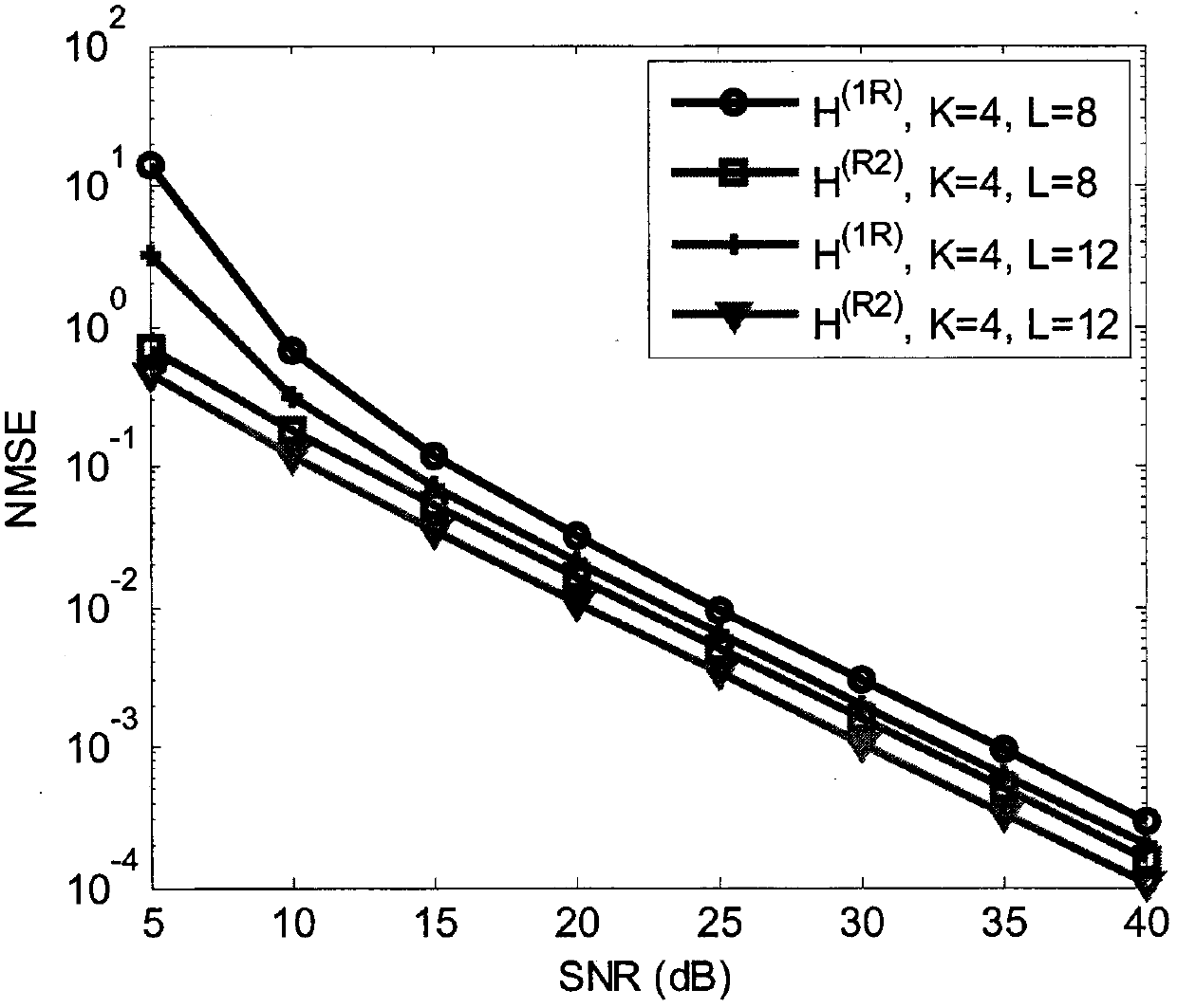
[0050] See image 3 , image 3 is a channel estimation performance diagram of the present invention under different channel training sequence lengths L. The system parameters are: M 1 = M 2 = 3, M R =3, the channel correlation coefficient ρ=0. image 3 It shows that with the increase of the length of the pilot training signal, the NMSE of the channel decreases accordingly. This is due to the increase of information used to estimate the channel, and the channel estimation accuracy of the proposed algorithm is improved.
Embodiment 2
[0052] See Figure 4 , Figure 4 is the channel estimation performance diagram of the present invention under different number K of channel training sequences. The system parameters are: M 1 = M 2 = 3, M R =3, ρ=0. Figure 4 It shows that with the increase of the number of pilot training signals, the NMSE of the channel decreases accordingly. Similarly, due to the increase in the number of pilot training signals, the information used to estimate the channel increases, and the estimation accuracy of the proposed algorithm is also improved.
Embodiment 3
[0054] See Figure 5 , Figure 5 It is a comparison chart of channel estimation performance between the present invention and existing methods when ρ=0.3.
[0055] The system parameters are: M 1 = M 2 = 3, M R =3, K=4, L=10, ρ=0.3. Figure 5 shows that for H (R2) The existing channel estimation method is better than the proposed method, because the existing method uses the relay to send the pilot signal to user 2, and directly estimates H at the user 2 end (R2) , so the performance is better than the proposed method. However, this method requires a separate estimation of the channel H at the user 2 end (R2) , and the proposed method can simultaneously estimate H (1R) and H (R2) . while for H (1R) , the proposed method is significantly better than the existing channel estimation methods. Because for the estimated H (1R) . The existing methods have the phenomenon of error propagation, but the proposed method is a joint estimation, which does not exist.
PUM
 Abstract
Description
Claims
Application Information